3D激光SLAM:ALOAM---后端lasermapping通过Ceres进行帧到地图的位姿优化
前言
上一篇博客构建了线约束和面约束,添加到了残差模块。
ALOAM:后端 lasermapping构建角点约束与面点约束
本片主要介绍通过ceres构建的约束的CostFuction,及后续的通过Ceres进行位姿优化
角点的约束添加在这个地方

这里的CostFunction是通过LidarEdgeFactor自定义的结构体建立的
和前端里程计用的角点约束是一样的在这篇博客中做了分析
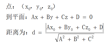
原理就是求当前点到a、b点构成的直线的距离作为残差
面点的约束添加在这个地方

输入参数有:
- curr_point 当前点
- norm 归一化得平面法向量
- negative_OA_dot_norm 法向量模的倒数
代码分析
然后可以分析 这个 LidarPlaneNormFactor 自定义的结构体了
struct LidarPlaneNormFactor
{

	LidarPlaneNormFactor(Eigen::Vector3d curr_point_, Eigen::Vector3d plane_unit_norm_,
						 double negative_OA_dot_norm_) : curr_point(curr_point_), plane_unit_norm(plane_unit_norm_),
														 negative_OA_dot_norm(negative_OA_dot_norm_) {}
- 1
- 2
- 3
- 4
- 5
- 6
构造函数,通过生成结构体时的参数,初始化三个变量,和上面的三个是一样的
- curr_point 当前点
- plane_unit_norm 归一化得平面法向量
- negative_OA_dot_norm 法向量模的倒数
	template <typename T>
	bool operator()(const T *q, const T *t, T *residual) const
	{
- 1
- 2
- 3
在前面说了分析Ceres的costfunction重点就是看这个重载()函数
参数模块在前,残差在后
Eigen::Quaternion<T> q_w_curr{q[3], q[0], q[1], q[2]};
- 1
把q转成 eigen的形式
Eigen::Matrix<T, 3, 1> t_w_curr{t[0], t[1], t[2]};
- 1
把t转成 eigen的形式
Eigen::Matrix<T, 3, 1> cp{T(curr_point.x()), T(curr_point.y()), T(curr_point.z())};
- 1
当前点 转成 eigen 的形式
		Eigen::Matrix<T, 3, 1> point_w;//当前点投影到局部地图坐标系下的点
		point_w = q_w_curr * cp + t_w_curr;//将当前点投影到局部地图坐标系下
- 1
- 2
q_w_curr和t_w_curr是当前帧到局部地图的位姿变换
上面的操作将当前点投影到局部地图上
		Eigen::Matrix<T, 3, 1> norm(T(plane_unit_norm.x()), T(plane_unit_norm.y()), T(plane_unit_norm.z()));
		residual[0] = norm.dot(point_w) + T(negative_OA_dot_norm);//求点到平面的距离
- 1
- 2
第一行就是把法向量转成eigen的形式
第二行就是求点到平面的距离
dot就是点乘,求解和前面说的一样

残差可以不取模,因为在ceres里面会平方的。
		return true;
	}
- 1
- 2
最后重载函数返回true即可
	static ceres::CostFunction *Create(const Eigen::Vector3d curr_point_, const Eigen::Vector3d plane_unit_norm_,
									   const double negative_OA_dot_norm_)
	{
		return (new ceres::AutoDiffCostFunction<
				LidarPlaneNormFactor, 1, 4, 3>(
			new LidarPlaneNormFactor(curr_point_, plane_unit_norm_, negative_OA_dot_norm_)));
	}
- 1
- 2
- 3
- 4
- 5
- 6
- 7
定义一个Creat函数,在里面实现AutoDiffCostFunction的定义,最后返回一个CostFunction
之后可以回到后端处理cpp—lasermapping.cpp中,在前面的博客添加了角点和面点约束,在上面分析了CostFunction,下面就是调用Ceres求解了
					// 调用Ceres求解
					TicToc t_solver;
					ceres::Solver::Options options;
					options.linear_solver_type = ceres::DENSE_QR;//稠密的问题 用DENSE_QR的求解方式
					options.max_num_iterations = 4;//最大迭代次数
					options.minimizer_progress_to_stdout = false;
					options.check_gradients = false;
					options.gradient_check_relative_precision = 1e-4;
					ceres::Solver::Summary summary;
					ceres::Solve(options, &problem, &summary);//求解
					printf("mapping solver time %f ms \n", t_solver.toc());//一次ceres求解的时间
- 1
- 2
- 3
- 4
- 5
- 6
- 7
- 8
- 9
- 10
- 11
就是Ceres的常规操作了, 由于涉及局部地图了,属于稠密问题,所以求解方式使用的DENSE_QR求解。最大迭代次数为4次。在终端打印一次ceres求解的时间。
Ceres优化时间测试
这优化过程中,在终端设置了这些的打印信息


分别是:
- 构建角点和面点约束的时间
- 一次ceres求解的时间
- 两次迭代优化用的时间
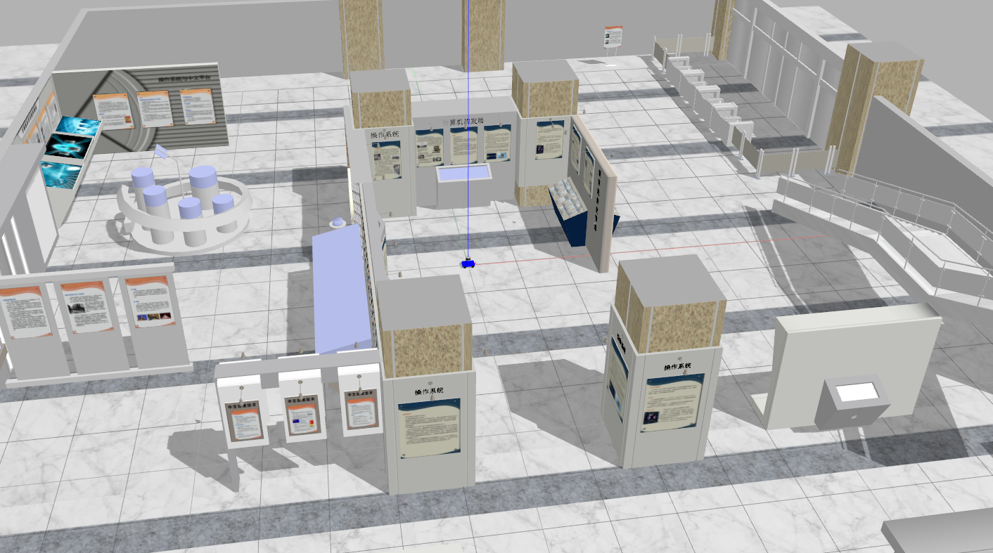
在这篇ALOAM:gazebo仿真测试场景搭建中搭建了测试场景,下面来测试下Ceres的优化时间是多少
场景是这样的,角点和面点很丰富

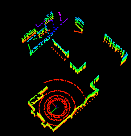
这个是ALOAM出的地图(AGV没动)

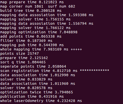
终端打印的数据(一帧)

局部地图提取的时间是0.12ms
局部地图中的角点数为1061 面点数是682
建立kd-tree的时间为0.20ms
构建角点和面点约束的时间为 1.59ms
一次ceres求解的时间为 1.75ms
两次迭代优化用的时间 为 7.04ms
文章来源: blog.csdn.net,作者:月照银海似蛟龙,版权归原作者所有,如需转载,请联系作者。
原文链接:blog.csdn.net/qq_32761549/article/details/125914299
- 点赞
- 收藏
- 关注作者


评论(0)