如何快速学会单片机编程并应用?

如何快速学会单片机编程并应用?
先上一些参考资料,主要来源知乎:
1 -怎样学会单片机?-
2 -arduino、arm、树莓派、单片机四者有什么不同?-
3 -单片机可以替代PLC么?-
4 -单片机有没有必要用汇编讲?-
5 -相关课程-
单片机和C语言,是自动化(机器人)学科重要的基础内容。
如果对机器人感兴趣,可参考机器人工程师学习计划。
课程学习动机~Why?为什么学习单片机编程?
单片机方向就业?把握市场需求!
软硬件能力的综合训练,电路原理图+软件编程(C语言)。
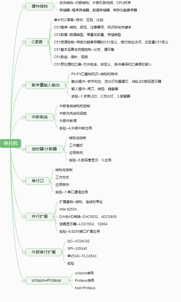
课程学习内容~What?单片机编程包括哪些内容?
目录和大纲,归纳和总结能力训练
课程学习方法~How?如何学习单片机编程?
在掌握基础知识后,仿真与实验。
Linux平台:MCU 8051 IDE
Windows平台:uVision+Proteus
扩展提升:在学完51单片机后,能够快速自学更为通用主流的嵌入式系统,如下:
C51--(Arduino、MSP430)--(2812、28335)--(STM32、ARM9)--(TK1、BeagleBone、Raspberry Pi)
那么问题来了,我们为什么不直接学习STM32等,而是要学习51呢?
其他参考资料:
-新更新考核材料和参考报告-
编程语言。
视频短片:
STEM教育 1 2 3 | ROS | 智慧家居 | 智能驾驶
模块化,低耦合 参考软件工程学
示例1 51+arduino
-
#include<reg51.h> //寄存器定义
-
#include<stdio.h> //一般I/O口定义
-
/***以下是全局变量定义*********/
-
sbit LED=P1^0; //LED灯连接在P1.0上
-
int data i; //定义一个整型全局变量
-
/*********主程序开始***************/
-
void main(void)
-
{ while(1)
-
{ LED=0; //LED灯点亮
-
for(i=0;i<1000;i++); //延时
-
LED=1; //LED灯熄灭
-
for(i=0;i<1000;i++); //延时
-
}
-
}
-
-
-
#include<reg51.h> //寄存器定义
-
#include<stdio.h> //一般I/O口定义
-
/***以下是全局变量定义*********/
-
sbit LED=P1^0; //LED灯连接在P1.0上
-
int data i; //定义一个整型全局变量
-
LED_demo() //LED函数
-
{ LED=0; //LED灯点亮
-
for(i=0;i<1000;i++); //延时
-
LED=1; //LED灯熄灭
-
for(i=0;i<1000;i++); //延时
-
}
-
/*********主程序开始***************/
-
void main(void)
-
{ while(1)
-
{
-
LED_demo();
-
}
-
}
-
-
/*
-
Blink
-
Turns on an LED on for one second, then off for one second, repeatedly.
-
-
Most Arduinos have an on-board LED you can control. On the UNO, MEGA and ZERO
-
it is attached to digital pin 13, on MKR1000 on pin 6. LED_BUILTIN is set to
-
the correct LED pin independent of which board is used.
-
If you want to know what pin the on-board LED is connected to on your Arduino model, check
-
the Technical Specs of your board at https://www.arduino.cc/en/Main/Products
-
-
This example code is in the public domain.
-
-
modified 8 May 2014
-
by Scott Fitzgerald
-
-
modified 2 Sep 2016
-
by Arturo Guadalupi
-
-
modified 8 Sep 2016
-
by Colby Newman
-
*/
-
-
-
// the setup function runs once when you press reset or power the board
-
void setup() {
-
// initialize digital pin LED_BUILTIN as an output.
-
pinMode(LED_BUILTIN, OUTPUT);
-
}
-
-
// the loop function runs over and over again forever
-
void loop() {
-
digitalWrite(LED_BUILTIN, HIGH); // turn the LED on (HIGH is the voltage level)
-
delay(1000); // wait for a second
-
digitalWrite(LED_BUILTIN, LOW); // turn the LED off by making the voltage LOW
-
delay(1000); // wait for a second
-
}
示例2 51+arduino
-
#include<reg52.h> //预处理命令,reg52.h是一个头文件
-
#include<stdio.h>
-
void Function1(void); //自定义函数Function1声明
-
unsigned int ch;//全局变量声明
-
-
void main(void) //主函数
-
{
-
-
-
SCON=0x50; //SCON:模式1,8bit异步串口通信
-
TMOD=0x20; //TMOD:定时器1为模式2,8bit自动装载方式
-
TH1=221; //TH1:1200bit/s的装载值,16MHz
-
TR1=1; //TR1:timer1运行
-
TI=1; //TI:设置为1,以发送第一个字节
-
-
while(ch<=5)
-
{
-
Function1( );//调用自定义函数
-
printf("char=%d\n",ch);//程序语句
-
}
-
while(1);
-
}
-
void Function1(void) //自定义函数Function1
-
{
-
unsigned char ps; //自定义函数内部变量声明
-
ps=1;
-
ch=ch+ps;
-
}
-
-
-
#include<reg52.h> //预处理命令,reg52.h是一个头文件
-
#include<stdio.h>
-
void Function1(void); //自定义函数Function1声明
-
void Init1(void);
-
unsigned int ch;//全局变量声明
-
-
void main(void) //主函数
-
{
-
Init1();
-
while(ch<=5)
-
{
-
Function1( );//调用自定义函数
-
printf("char=%d\n",ch);//程序语句
-
}
-
while(1);
-
}
-
void Function1(void) //自定义函数Function1
-
{
-
unsigned char ps; //自定义函数内部变量声明
-
ps=1;
-
ch=ch+ps;
-
}
-
void Init1(void)
-
{
-
-
-
SCON=0x50; //SCON:模式1,8bit异步串口通信
-
TMOD=0x20; //TMOD:定时器1为模式2,8bit自动装载方式
-
TH1=221; //TH1:1200bit/s的装载值,16MHz
-
TR1=1; //TR1:timer1运行
-
TI=1; //TI:设置为1,以发送第一个字节
-
}
-
-
-
/*
-
Serial Call and Response in ASCII
-
Language: Wiring/Arduino
-
-
This program sends an ASCII A (byte of value 65) on startup
-
and repeats that until it gets some data in.
-
Then it waits for a byte in the serial port, and
-
sends three ASCII-encoded, comma-separated sensor values,
-
truncated by a linefeed and carriage return,
-
whenever it gets a byte in.
-
-
Thanks to Greg Shakar and Scott Fitzgerald for the improvements
-
-
The circuit:
-
* potentiometers attached to analog inputs 0 and 1
-
* pushbutton attached to digital I/O 2
-
-
-
-
Created 26 Sept. 2005
-
by Tom Igoe
-
modified 24 Apr 2012
-
by Tom Igoe and Scott Fitzgerald
-
-
This example code is in the public domain.
-
-
http://www.arduino.cc/en/Tutorial/SerialCallResponseASCII
-
-
*/
-
-
int firstSensor = 0; // first analog sensor
-
int secondSensor = 0; // second analog sensor
-
int thirdSensor = 0; // digital sensor
-
int inByte = 0; // incoming serial byte
-
-
void setup() {
-
// start serial port at 9600 bps and wait for port to open:
-
Serial.begin(9600);
-
while (!Serial) {
-
; // wait for serial port to connect. Needed for native USB port only
-
}
-
-
-
pinMode(2, INPUT); // digital sensor is on digital pin 2
-
establishContact(); // send a byte to establish contact until receiver responds
-
}
-
-
void loop() {
-
// if we get a valid byte, read analog ins:
-
if (Serial.available() > 0) {
-
// get incoming byte:
-
inByte = Serial.read();
-
// read first analog input:
-
firstSensor = analogRead(A0);
-
// read second analog input:
-
secondSensor = analogRead(A1);
-
// read switch, map it to 0 or 255L
-
thirdSensor = map(digitalRead(2), 0, 1, 0, 255);
-
// send sensor values:
-
Serial.print(firstSensor);
-
Serial.print(",");
-
Serial.print(secondSensor);
-
Serial.print(",");
-
Serial.println(thirdSensor);
-
}
-
}
-
-
void establishContact() {
-
while (Serial.available() <= 0) {
-
Serial.println("0,0,0"); // send an initial string
-
delay(300);
-
}
-
}
-
其他參考資料:http://blog.csdn.net/zhangrelay/article/details/52336300
文章来源: zhangrelay.blog.csdn.net,作者:zhangrelay,版权归原作者所有,如需转载,请联系作者。
原文链接:zhangrelay.blog.csdn.net/article/details/53841916

- 点赞
- 收藏
- 关注作者
评论(0)