【 FPGA 】认识关键BUFFER
目录
内容参考自:
Vivado Design Suite 7 Series FPGA and Zynq-7000 All Programmable SoC Libraries Guide
UG953 (v2017.2) August 10, 2017
BUFG
介绍

此设计元素是一个高扇出缓冲区,用于将信号连接到全局布线资源以实现信号的低偏斜分布。
BUFG通常用于时钟网络以及其他高扇出网络,如置位/复位和时钟使能。
Verilog Instantiation Template
// BUFG: Global Clock Simple Buffer
// 7 Series
// Xilinx HDL Libraries Guide, version 2017.2
BUFG BUFG_inst (
.O(O), // 1-bit output: Clock output
.I(I) // 1-bit input: Clock input
);
// End of BUFG_inst instantiation
博文:时钟树简介 讲到了时钟上树的问题,如何选择时钟树问题,可以参考:例如
如果FPGA内部有一个名为innerClk的时钟信号,我们想为它分配一个全局时钟树,Verilog HDL描述为:
wire globalClk;
BUFG onTree(.O(globalClk), .I(innerClk));
按照上述HDL代码描述以后,我们就可以在后续的逻辑功能中放心使用上树后的innerClk——globalClk了。
实际上,直接从外部全局时钟管脚引入的时钟信号,相当于在HDL代码中使用了IBUF + BUFG原语。
除此之外,如果希望多个时钟信号分享一个时钟树,也可以使用BUGMUX这个原语,相当于MUX +BUFG,例如,希望当前FPGA设计中的某一部分逻辑其时钟是可以在40Hz和60Hz之间切换的。
---------------------
作者:李锐博恩(Reborn)
来源:CSDN
原文:https://blog.csdn.net/Reborn_Lee/article/details/84564542
版权声明:本文为博主原创文章,转载请附上博文链接!
IBUF
介绍

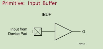
该设计元素由综合工具自动插入(推断)到直接连接到设计的顶级输入或双向端口的任何信号。 您通常应该让综合工具推断出这个缓区。 但是,如果需要,可以将其实例化到设计中。
Verilog Instantiation Template
// IBUF: Single-ended Input Buffer
// 7 Series
// Xilinx HDL Libraries Guide, version 2017.2
IBUF #(
.IBUF_LOW_PWR("TRUE"), // Low power (TRUE) vs. performance (FALSE) setting for referenced I/O standards
.IOSTANDARD("DEFAULT") // Specify the input I/O standard
) IBUF_inst (
.O(O), // Buffer output
.I(I) // Buffer input (connect directly to top-level port)
);
// End of IBUF_inst instantiation
IBUFDS

Introduction
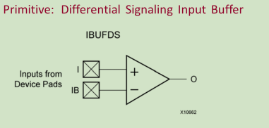
This design element is an input buffer that supports low-voltage, differential signaling. In IBUFDS, a design level interface signal is represented as two distinct ports (I and IB), one deemed the "master" and the other the "slave." The master and the slave are opposite phases of the same logical signal (for example, MYNET_P and MYNET_N). Optionally, a programmable differential termination feature is available to help improve signal integrity and reduce external components.
该设计元素是一个支持低电压差分信号的输入缓冲器。 在IBUFDS中,设计级接口信号表示为两个不同的端口(I和IB),一个视为“主”,另一个视为“从”。 主机和从机是相同逻辑信号的相位相反(例如,MYNET_P和MYNET_N)。 可选的,可编程差分端接功能可用于帮助改善信号完整性并减少外部元件。

Verilog Instantiation Template
// IBUFDS: Differential Input Buffer
// 7 Series
// Xilinx HDL Libraries Guide, version 2017.2
IBUFDS #(
.DIFF_TERM("FALSE"), // Differential Termination
.IBUF_LOW_PWR("TRUE"), // Low power="TRUE", Highest performance="FALSE"
.IOSTANDARD("DEFAULT") // Specify the input I/O standard
) IBUFDS_inst (
.O(O), // Buffer output.I(I), // Diff_p buffer input (connect directly to top-level port)
.IB(IB) // Diff_n buffer input (connect directly to top-level port)
);
// End of IBUFDS_inst instantiation
BUFGMUX

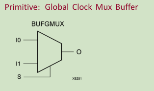
该设计元素是一个全局时钟缓冲器,可以在两个输入时钟之间进行选择:I0和I1。 当选择输入(S)为低时,选择I0上的信号作为输出(O)。 当选择输入(S)为高电平时,选择I1上的信号进行输出。

Verilog Instantiation Template
// BUFGMUX: Global Clock Mux Buffer
// 7 Series
// Xilinx HDL Libraries Guide, version 2017.2
BUFGMUX #(
)
BUFGMUX_inst (
.O(O), // 1-bit output: Clock output
.I0(I0), // 1-bit input: Clock input (S=0)
.I1(I1), // 1-bit input: Clock input (S=1)
.S(S) // 1-bit input: Clock select
);
// End of BUFGMUX_inst instantiation
BUFH

The BUFH primitive allows direct access to the clock region entry point of the global buffer (BUFG) resource. This allows access to unused portions of the global clocking network to be used as high-speed, low skew local (single clock region) routing resources. Refer to the 7 series FPGA Clocking Resources User Guide for details about using this component.
BUFH原语允许直接访问全局缓冲区(BUFG)资源的时钟区域入口点。 这允许访问全局时钟网络的未使用部分以用作高速,低偏斜本地(单时钟区域)布线资源。
Verilog Instantiation Template
// BUFH: HROW Clock Buffer for a Single Clocking Region
// 7 Series
// Xilinx HDL Libraries Guide, version 2017.2
BUFH BUFH_inst (
.O(O), // 1-bit output: Clock output
.I(I) // 1-bit input: Clock input
);
// End of BUFH_inst instantiation
BUFIO

该设计元素是本地时钟输入,时钟输出缓冲器。 它在I / O列内驱动专用时钟网络,与全局时钟资源无关,非常适合源同步数据捕获(转发/接收器时钟分配)。 BUFIO元件可以由位于相同时钟区域的专用MRCC I / O驱动,或者由能够为多个时钟区域提供时钟的BUFMRCE / BUFMR组件驱动。 BUFIO只能驱动存在的存储区中的I / O组件。 它们不能直接驱动逻辑资源(CLB,Block RAM等),因为I / O时钟网络只到达I / O列。
Verilog Instantiation Template
// BUFIO: Local Clock Buffer for I/O
// 7 Series
// Xilinx HDL Libraries Guide, version 2017.2
BUFIO BUFIO_inst (
.O(O), // 1-bit output: Clock output (connect to I/O clock loads).
.I(I) // 1-bit input: Clock input (connect to an IBUF or BUFMR).
);
// End of BUFIO_inst instantiation
BUFR

BUFR是7系列器件中的区域时钟缓冲器,可将时钟信号驱动到时钟区域内的专用时钟网络,与全局时钟树无关。每个BUFR可以驱动其所在区域的区域时钟网络。与BUFIO组件不同,BUFR组件可以驱动现有时钟区域中的I / O逻辑和逻辑资源(CLB,Block RAM等)。它们可以由IBUF,BUFMRCE,MMCM或本地互连的输出驱动,并且能够生成相对于时钟输入的分频时钟输出。除数值是1到8之间的整数。 BUFR组件非常适用于需要时钟域交叉或串并转换的源同步应用。典型时钟区域中有两个BUFR组件(两个区域时钟网络)。如果在多个时钟区域中需要本地时钟,则BUFMRCE可以驱动相邻时钟区域中的多个BUFR组件,以进一步扩展该时钟功能。有关详细信息,请参阅BUFMRCE。

Verilog Instantiation Template
// BUFR: Regional Clock Buffer for I/O and Logic Resources within a Clock Region
// 7 Series
// Xilinx HDL Libraries Guide, version 2017.2
BUFR #(
.BUFR_DIVIDE("BYPASS"), // Values: "BYPASS, 1, 2, 3, 4, 5, 6, 7, 8"
.SIM_DEVICE("7SERIES") // Must be set to "7SERIES"
)
BUFR_inst (
.O(O), // 1-bit output: Clock output port
.CE(CE), // 1-bit input: Active high, clock enable (Divided modes only)
.CLR(CLR), // 1-bit input: Active high, asynchronous clear (Divided modes only)
.I(I) // 1-bit input: Clock buffer input driven by an IBUF, MMCM or local interconnect);
// End of BUFR_inst instantiation
BUFMRCE

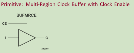
The BUFMRCE is a multi-region clock-in/clock-out buffer with clock with clock enable (CE). Asserting CE stops the output clock to a user specified value. The BUFMRCE replaces the multi-region/bank support of the BUFR and BUFIO available in prior Virtex architectures. There are two BUFMRCEs in every bank and each buffer can be driven by one specific MRCC in the same bank. The BUFMRCE drives the BUFIOs and/or BUFRs in the same region/banks and in the region above and below via the I/O clocking backbone. When using BUFR dividers (not in bypass), the BUFMRCE must be disabled by deasserting the CE pin, the BUFR must be reset (cleared by asserting CLR), and then the CE signal should be asserted. This sequence ensures that all BUFR output clocks are phase aligned. If the dividers within the BUFRs are not used, then this additional circuitry is not necessary. If the clock enable circuitry is not needed, a BUFMR component should be used in place of a BUFMRCE.
BUFMRCE是一个多区域时钟输入/输出缓冲器,具有时钟使能(CE)时钟。 假定CE会将输出时钟停止为用户指定的值。 BUFMRCE取代了先前Virtex架构中可用的BUFR和BUFIO的多区域/ bank支持。 每个库中有两个BUFMRCE,每个缓冲区可以由同一个库中的一个特定MRCC驱动。 BUFMRCE通过I / O时钟主干驱动相同区域/组中以及上下区域中的BUFIO和/或BUFR。 当使用BUFR分频器(不在旁路)时,必须通过置低CE引脚来禁用BUFMRCE,必须复位BUFR(通过置位CLR清零),然后应该置位CE信号。 此序列确保所有BUFR输出时钟都是相位对齐的。 如果不使用BUFR内的分频器,则不需要该附加电路。 如果不需要时钟使能电路,则应使用BUFMR组件代替BUFMRCE。


Verilog Instantiation Template
// BUFMRCE: Multi-Region Clock Buffer with Clock Enable
// 7 Series
// Xilinx HDL Libraries Guide, version 2017.2
BUFMRCE #(
.CE_TYPE("SYNC"), // SYNC, ASYNC
.INIT_OUT(0) // Initial output and stopped polarity, (0-1)
)
BUFMRCE_inst (
.O(O), // 1-bit output: Clock output (connect to BUFIOs/BUFRs)
.CE(CE), // 1-bit input: Active high buffer enable
.I(I) // 1-bit input: Clock input (Connect to IBUF)
);
// End of BUFMRCE_inst instantiation
文章来源: reborn.blog.csdn.net,作者:李锐博恩,版权归原作者所有,如需转载,请联系作者。
原文链接:reborn.blog.csdn.net/article/details/85004519
- 点赞
- 收藏
- 关注作者


评论(0)