HDLBits 系列(30)Serial Receiver

目录
序言
所谓的串行接收器(Serial Receiver),类似,或者根本就是Uart的协议的一种形式,Uart的接收器部分,如何实现呢?
原题复现
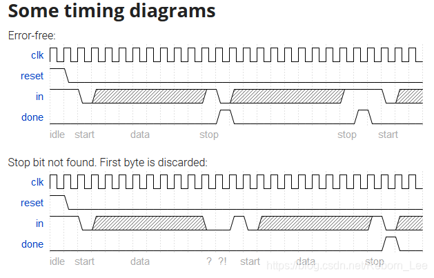
In many (older) serial communications protocols, each data byte is sent along with a start bit and a stop bit, to help the receiver delimit bytes from the stream of bits. One common scheme is to use one start bit (0), 8 data bits, and 1 stop bit (1). The line is also at logic 1 when nothing is being transmitted (idle).
Design a finite state machine that will identify when bytes have been correctly received when given a stream of bits. It needs to identify the start bit, wait for all 8 data bits, then verify that the stop bit was correct. If the stop bit does not appear when expected, the FSM must wait until it finds a stop bit before attempting to receive the next byte.
翻译
翻译下就是:
在许多(较旧的)串行通信协议中,每个数据字节都与起始位和停止位一起发送,以帮助接收器从位流中分隔字节。 一种常见的方案是使用一个起始位(0),8个数据位和1个停止位(1)。 当没有任何传输(空闲)时,线路也处于逻辑1。
设计一个有限状态机,当给定比特流时,它将识别何时正确接收了字节。 它需要标识起始位,等待所有8个数据位,然后验证停止位是否正确。 如果在预期的情况下没有出现停止位,则FSM必须等待直到找到停止位,然后再尝试接收下一个字节。
状态转移图
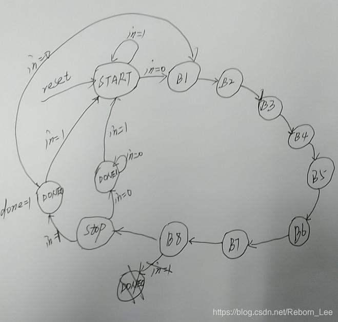
根据描述,我们设计一个状态转移图:
我的设计
根据此状态转移图,可以很容易给出我们的设计:
-
module top_module(
-
input clk,
-
input in,
-
input reset, // Synchronous reset
-
output done
-
);
-
localparam START = 0, B1 = 1, B2 = 2, B3 = 3, B4 = 4, B5 = 5, B6 = 6, B7 = 7, B8 = 8, STOP = 9, DONE0 = 10, DONE1 = 11;
-
reg [3:0] state, next_state;
-
always@(*) begin
-
case(state)
-
START: begin
-
if(in == 0) next_state = B1;
-
else next_state = START;
-
end
-
B1: begin
-
next_state = B2;
-
end
-
B2: begin
-
next_state = B3;
-
end
-
B3: begin
-
next_state = B4;
-
end
-
B4: begin
-
next_state = B5;
-
end
-
B5: begin
-
next_state = B6;
-
end
-
B6: begin
-
next_state = B7;
-
end
-
B7: begin
-
next_state = B8;
-
end
-
B8: begin
-
next_state = STOP;
-
end
-
STOP: begin
-
if(in == 0) next_state = DONE1;
-
else next_state = DONE0;
-
end
-
DONE0: begin
-
if(in == 1) next_state = START;
-
else next_state = B1;
-
end
-
DONE1: begin
-
if(in == 0) next_state = DONE1;
-
else next_state = START;
-
end
-
default: begin
-
next_state = START;
-
end
-
-
endcase
-
end
-
-
always@(posedge clk) begin
-
if(reset) state <= START;
-
else state <= next_state;
-
end
-
-
assign done = (state == DONE0) ? 1 : 0;
-
-
-
-
endmodule
测试正确。
设计解释
需要注意的是最后一步的设计,也就是STOP状态之后的判断,如果输入数据为1,则数据接受结束,给出接受完毕信号done;否则的话,我们不得不等到结束位标志1之后才能进入下一串数据的接收,且一旦进入这种情况,则抛弃这一串数据的接受,也即不会产生接受完毕信号done。
最后不得不说的是,Uart接受协议可以有多个结束位,甚至还可以有校验位等,一旦确认了协议,我们就可以编写类似的代码来实现数据的接收。
文章来源: reborn.blog.csdn.net,作者:李锐博恩,版权归原作者所有,如需转载,请联系作者。
原文链接:reborn.blog.csdn.net/article/details/103438860

- 点赞
- 收藏
- 关注作者
评论(0)