HDLBits 系列(38)值得一看的状态机设计题目

目录
背景
这是这个系列中的一个状态机的题目,但是相比于给了你完整状态转移图之类的题目,这个题目还是稍微有点难的,我实在不知道该怎么给这个博客起个什么名字?
我在线等一个简单的方式去解决今天的问题,而如题所说,我用最无能的方式来解决这个问题,但简单的方式一定存在。
2019/12/16更新
今天一个帅兄弟给了我一个答案,很巧妙,这里十分感谢。我把它放到后面来给出。
原题复现
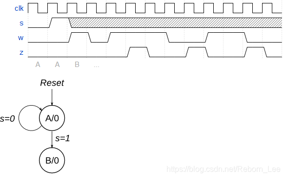
Consider a finite state machine with inputs s and w. Assume that the FSM begins in a reset state called A, as depicted below. The FSM remains in state A as long as s = 0, and it moves to state B when s = 1. Once in state B the FSM examines the value of the input w in the next three clock cycles. If w = 1 in exactly two of these clock cycles, then the FSM has to set an output z to 1 in the following clock cycle. Otherwise z has to be 0. The FSM continues checking w for the next three clock cycles, and so on. The timing diagram below illustrates the required values of z for different values of w.
Use as few states as possible. Note that the s input is used only in state A, so you need to consider just the w input.
我的方案
状态转移图
我的解决方案,有点无奈,多加了一些状态:

我的设计
根据此状态转移图给出我的设计:
-
module top_module (
-
input clk,
-
input reset, // Synchronous reset
-
input s,
-
input w,
-
output z
-
);
-
-
localparam A = 0, B = 1, S0 = 3, S1 = 4, S2 = 5, S3 = 6, S4 = 7, S5 = 8, S6 = 9, S7 = 10, S8 = 11, S9 = 12, S10 = 13, S11 = 14;
-
reg [3:0] state, next_state;
-
always@(*) begin
-
case(state)
-
A: begin
-
if(s) next_state = B;
-
else next_state = A;
-
end
-
B: begin
-
if(w) next_state = S1;
-
else next_state = S0;
-
end
-
S0: begin
-
if(w) next_state = S2;
-
else next_state = S4;
-
end
-
S1: begin
-
if(w) next_state = S9;
-
else next_state = S6;
-
end
-
S2: begin
-
if(w) next_state = S3;
-
else next_state = S5;
-
end
-
S3: begin
-
if(w) next_state = S1;
-
else next_state = S0;
-
end
-
S4: begin
-
next_state = S5;
-
end
-
S5: begin
-
if(w) next_state = S1;
-
else next_state = S0;
-
end
-
S6: begin
-
if(w) next_state = S7;
-
else next_state = S8;
-
end
-
S7: begin
-
if(w) next_state = S1;
-
else next_state = S0;
-
end
-
S8: begin
-
if(w) next_state = S1;
-
else next_state = S0;
-
end
-
S9: begin
-
if(w) next_state = S11;
-
else next_state = S10;
-
end
-
S10: begin
-
if(w) next_state = S1;
-
else next_state = S0;
-
end
-
S11: begin
-
if(w) next_state = S1;
-
else next_state = S0;
-
end
-
default: begin
-
next_state = A;
-
end
-
-
endcase
-
-
end
-
always@(posedge clk) begin
-
if(reset) state <= 0;
-
else state <= next_state;
-
end
-
assign z = (state == S10 || state == S7 || state == S3) ? 1 : 0;
-
-
-
-
-
-
endmodule
测试成功。
更新方案
今天群里的大佬给了一种简单的方法,状态转移图确实简单了,但是理解起来呢?
我之前用的方案是在B之后的三个周期内,列举w的值,取值情况有8种,然后添加更多的状态去解决这个问题,不得不说状态转移图看起来复杂很多,也绝对不是推荐的方案。
我等待的确实是今天的这个方案,通过计数,不需要添加更多的状态,这也是我一开始就想用的方法,只是计数的时序当时没有搞定,今天很感谢,群里的一位兄弟。
直接给出设计,通过代码就应该能看出来设计的思路:
-
module top_module (
-
input clk,
-
input reset, // Synchronous reset
-
input s,
-
input w,
-
output z
-
);
-
parameter A = 1'b0, B = 1'b1;
-
reg current_state;
-
reg next_state;
-
-
always@(posedge clk)begin
-
if(reset)begin
-
current_state <= A;
-
end
-
else begin
-
current_state <= next_state;
-
end
-
end
-
-
always@(*)begin
-
case(current_state)
-
A:begin
-
next_state = s ? B : A;
-
end
-
B:begin
-
next_state = B;
-
end
-
endcase
-
end
-
-
reg w_reg1;
-
reg w_reg2;
-
always@(posedge clk)begin
-
if(reset)begin
-
w_reg1 <= 1'b0;
-
w_reg2 <= 1'b0;
-
end
-
else if(next_state == B)begin
-
w_reg1 <= w;
-
w_reg2 <= w_reg1;
-
end
-
else begin
-
w_reg1 <= 1'b0;
-
w_reg2 <= 1'b0;
-
end
-
end
-
-
always@(posedge clk)begin
-
if(reset)begin
-
z <= 1'b0;
-
end
-
else if(next_state == B && counter == 2'd0)begin
-
if(~w & w_reg1 & w_reg2 | w & ~w_reg1 & w_reg2 | w & w_reg1 & ~w_reg2)begin
-
z <= 1'b1;
-
end
-
else begin
-
z <= 1'b0;
-
end
-
end
-
else begin
-
z <= 1'b0;
-
end
-
end
-
-
reg [1:0] counter;
-
always@(posedge clk)begin
-
if(reset)begin
-
counter <= 2'd0;
-
end
-
else if(counter == 2'd2)begin
-
counter <= 2'd0;
-
end
-
else if(next_state == B)begin
-
counter <= counter + 1'b1;
-
end
-
end
-
-
endmodule
巧妙之处在于将输入w延迟两拍之后进行判断,如果有两个w为1,则在下一个周期将输出z置位.
有的朋友,也许在状态机的设计中,习惯将第三段使用组合逻辑来实现,这个题目的第三段也可以使用组合逻辑,但是呢?确实也没有必要,因为状态机的第三段本身既可以使用组合逻辑,也可以使用时序逻辑,如果使用时序逻辑。
下面给出组合逻辑的方案:
-
module top_module (
-
input clk,
-
input reset, // Synchronous reset
-
input s,
-
input w,
-
output reg z
-
);
-
parameter A = 1'b0, B = 1'b1;
-
reg current_state;
-
reg next_state;
-
-
always@(posedge clk)begin
-
if(reset)begin
-
current_state <= A;
-
end
-
else begin
-
current_state <= next_state;
-
end
-
end
-
-
always@(*)begin
-
case(current_state)
-
A:begin
-
next_state = s ? B : A;
-
end
-
B:begin
-
next_state = B;
-
end
-
endcase
-
end
-
-
reg w_reg1;
-
reg w_reg2;
-
always@(posedge clk)begin
-
if(reset)begin
-
w_reg1 <= 1'b0;
-
w_reg2 <= 1'b0;
-
end
-
else if(next_state == B)begin
-
w_reg1 <= w;
-
w_reg2 <= w_reg1;
-
end
-
else begin
-
w_reg1 <= 1'b0;
-
w_reg2 <= 1'b0;
-
end
-
end
-
-
reg z_mid;
-
always@(*)begin
-
if(reset)begin
-
z_mid <= 1'b0;
-
end
-
else if(current_state == B && counter == 2'd0)begin
-
if(~w & w_reg1 & w_reg2 | w & ~w_reg1 & w_reg2 | w & w_reg1 & ~w_reg2)begin
-
z_mid <= 1'b1;
-
end
-
else begin
-
z_mid <= 1'b0;
-
end
-
end
-
else begin
-
z_mid <= 1'b0;
-
end
-
end
-
-
always@(posedge clk)begin
-
if(reset)begin
-
z <= 1'b0;
-
end
-
else begin
-
z <= z_mid;
-
end
-
end
-
-
-
reg [1:0] counter;
-
always@(posedge clk)begin
-
if(reset)begin
-
counter <= 2'd0;
-
end
-
else if(counter == 2'd2)begin
-
counter <= 2'd0;
-
end
-
else if(next_state == B)begin
-
counter <= counter + 1'b1;
-
end
-
end
-
-
endmodule
只需要将第三段改为组合逻辑,但是输出需要延迟一拍,为什么?看时序图。
FPGA/IC群推荐
有幸在这个群里认识了诸多俊杰,让我欣慰。
文章来源: reborn.blog.csdn.net,作者:李锐博恩,版权归原作者所有,如需转载,请联系作者。
原文链接:reborn.blog.csdn.net/article/details/103484037

- 点赞
- 收藏
- 关注作者
评论(0)