单片机|CC2530实验入门
本教程为实验入门,手把手教你编译一个工程
一、USB驱动
仿真器设备的连接
【说明】USB接口不够可以使用USB集线器扩展,且互相不会干扰,非常方便。
由于用到了CC仿真器(smart RF04EB),需要相关驱动。连接仿真器,之后通过系统找设备管理器,通过更新驱动程序,可以安装好仿真器,驱动路径:…\IAR Systems\Embedded Workbench 6.4\8051\drivers\Texas Instruments
二、IAR的安装、配置和测试
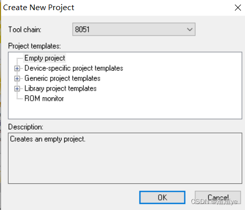
1.Project——>Create New Project,点击OK后命名,进入界面

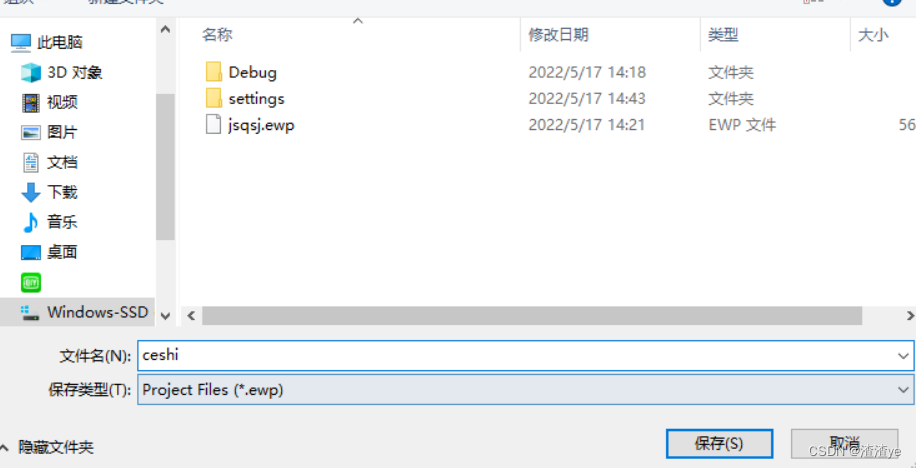
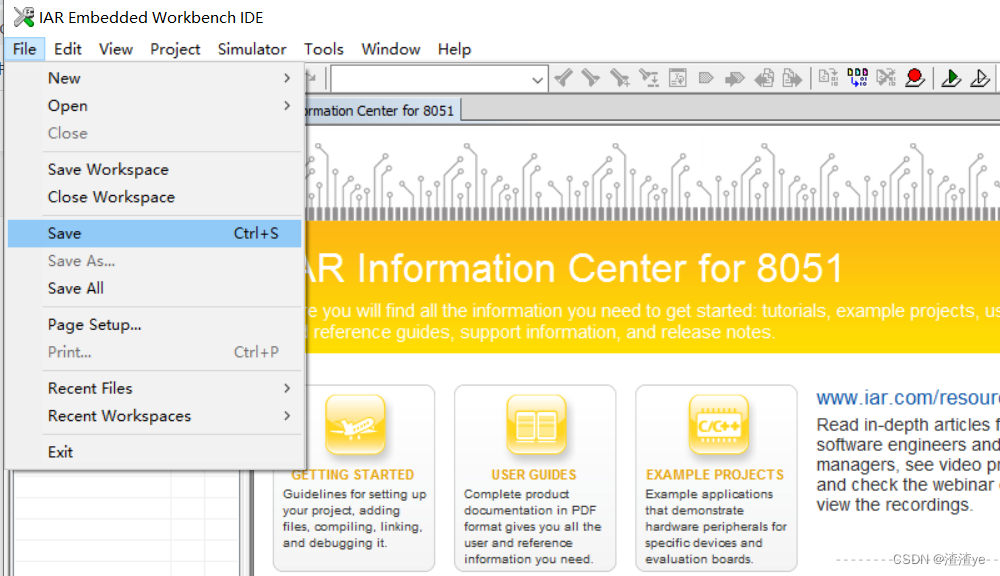
2.File——>Save Workspace,命名文件名
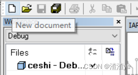
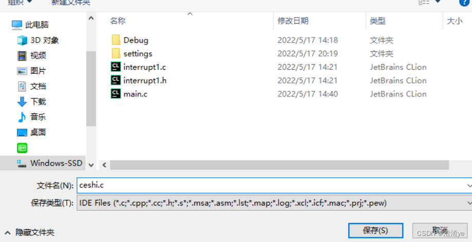
3.New document,保存后命名
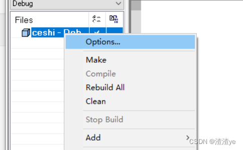
4.右键工程后选择Options,进行设置
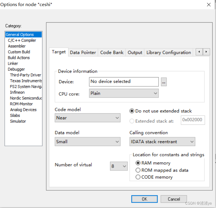
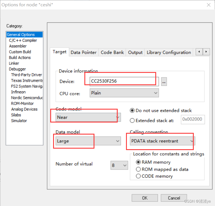
5.Gerenal Options中,Target的选项为:
Device:CC2530F256;
Code Mode:Near;
Data model:Large;
Calling convention:PDATA stack reentrant。
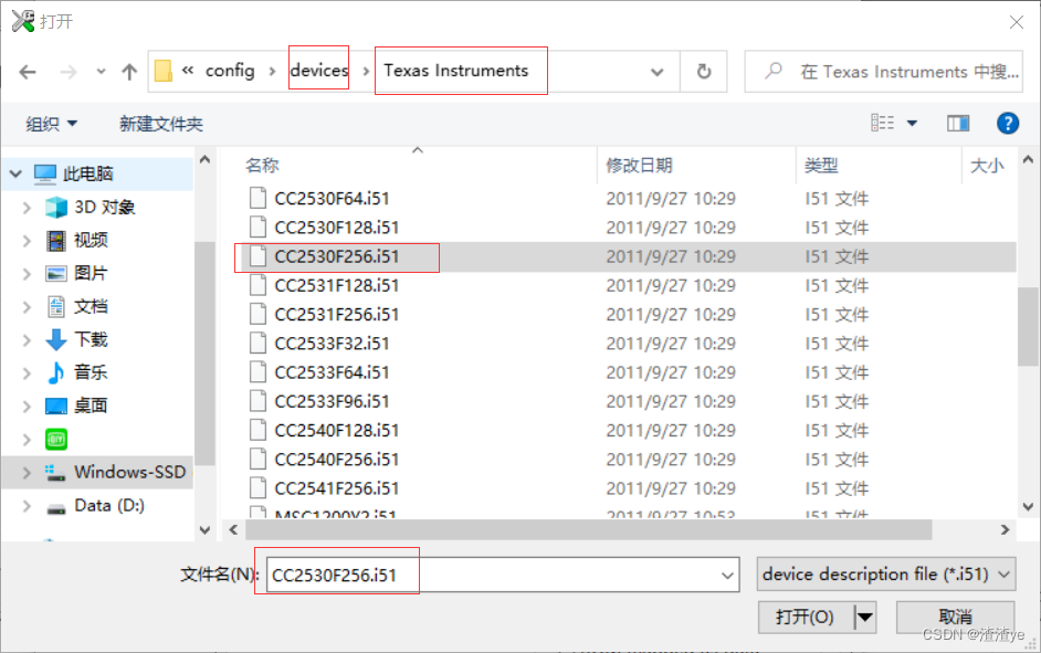
6.Linker设置:Linker command file:选择lnk51ew_cc2530F256.xcl

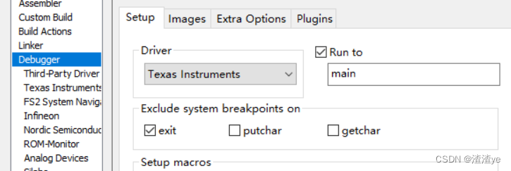
7.Debugger设置:Driver:Texas Instruments (本实验为真机调试,所以选择TI;若其他程序要使用IAR仿真器,可选Simulator)Device Description file:CC2530F256.ddf(可以不选)
之后保存,由于配置过了,因此IDE会把该工程的配置信息保存成workspace。

三、运行
1.放入代码
-
#include <ioCC2530.h>
-
typedef unsigned char uchar;
-
typedef unsigned int uint;
-
#define LED1 P1_0
-
void Delay(uint msec) //延时
-
{
-
uint i,j;
-
for(i=0;i<msec;i++)
-
for(j=0;j<10000;j++){}
-
}
-
void Led_Init()
-
{
-
P1SEL&=~(1<<0);
-
P1DIR|=(1<<0);
-
}
-
-
void main()
-
{
-
Led_Init();
-
while(1)
-
{
-
LED1=0;
-
Delay(10);
-
LED1=1;
-
Delay(100);
-
}
-
}
2.Compile -> Make -> Download,然后 菜单 -> Debug -> Go
之后可看到LED反应。此时去掉仿真器,通电,该模块还是如此。程序已经下载到开发板中
完成部署
文章来源: blog.csdn.net,作者:渣渣ye,版权归原作者所有,如需转载,请联系作者。
原文链接:blog.csdn.net/yyfloveqcw/article/details/124829039
- 点赞
- 收藏
- 关注作者



评论(0)