平面2R机器人(二连杆)运动学与动力学建模+附仿真模型

举报
Mr.Winter 发表于 2022/03/22 19:11:46 2022/03/22
【摘要】 平面2R机器人运动学与动力学建模+附仿真模型

在这里插入图片描述


1 平面2R机器人概述

如图1所示为本文的研究本体——平面2R机器人。对参数进行如下定义:机器人广义坐标 θ 1 \theta _1 为连杆1与 y y 轴负半轴的夹角,逆时针为正; θ 2 \theta _2 为连杆2与连杆1延长线的夹角,逆时针为正;连杆1、2的关节力矩分别定义为 τ 1 \tau_1 τ 2 \tau_2 。设连杆质量均匀分布,长度都为 l l ,质量都为 M M ,末端执行器笛卡尔坐标为 P ( x , y ) P(x,y)

在这里插入图片描述

图1

2 运动学建模

2.1 正运动学模型

指数积方法的核心原理是基于运动旋量的==指数积公式==:

T A T ( θ ) = e [ V 1 ] θ 1 e [ V 2 ] θ 2 e [ V n ] θ n T A T ( 0 ) _{\boldsymbol{T}}^{\boldsymbol{A}}\boldsymbol{T}\left( \boldsymbol{\theta } \right) =e^{\left[ \boldsymbol{V}_1 \right] \theta _1}e^{\left[ \boldsymbol{V}_2 \right] \theta _2}\cdots {e^{\left[ \boldsymbol{V}_n \right] \theta _n}}_{\boldsymbol{T}}^{\boldsymbol{A}}\boldsymbol{T}\left( 0 \right)

可以证明,连杆变换之积(DH法)等价于指数积。对平面2R机器人,确定各个关节轴线的线矢量如图2所示,不必建立连杆坐标系。

在这里插入图片描述

图2

各轴线方向如下:
$$\omega _1=\omega _2=\left[ \begin{array}{c} 0\ 0\ 1\\end{array} \right] ,\mathrm{ }\left[ \omega _1 \right] =\left[ \omega _2 \right] =\left[ \begin{matrix} 0& -1& 0\ 1& 0& 0\ 0& 0& 0\\end{matrix} \right]$$

取各个运动轴上的一点:

r 1 = [ 0 0 0 ] , r 2 = [ 0 l 0 ] r_1=\left[ \begin{array}{c} 0\\ 0\\ 0\\\end{array} \right] ,\mathrm{ }r_2=\left[ \begin{array}{c} 0\\ -l\\ 0\\\end{array} \right]

可得各个运动旋量的指数形式

e [ V 1 ] θ 1 = [ cos θ 1 sin θ 1 0 0 sin θ 1 cos θ 1 0 0 0 0 1 0 0 0 0 1 ] , e [ V 2 ] θ 2 = [ cos θ 2 sin θ 2 0 l sin θ 2 sin θ 2 cos θ 2 0 l ( 1 cos θ 2 ) 0 0 1 0 0 0 0 1 ] e^{\left[ \boldsymbol{V}_1 \right] \theta _1}=\left[ \begin{matrix} \cos \theta _1& -\sin \theta _1& 0& 0\\ \sin \theta _1& \cos \theta _1& 0& 0\\ 0& 0& 1& 0\\ 0& 0& 0& 1\\\end{matrix} \right] , e^{\left[ \boldsymbol{V}_2 \right] \theta _2}=\left[ \begin{matrix} \cos \theta _2& -\sin \theta _2& 0& -l\sin \theta _2\\ \sin \theta _2& \cos \theta _2& 0& -l\left( 1-\cos \theta _2 \right)\\ 0& 0& 1& 0\\ 0& 0& 0& 1\\\end{matrix} \right]

关节变量 θ = [ θ 1 θ 2 ] \boldsymbol{\theta }=\left[ \begin{matrix} \theta _1& \theta _2\\\end{matrix} \right] 为0时即为初始位姿:

T B T ( 0 ) = [ 1 0 0 0 0 1 0 2 l 0 0 1 0 0 0 0 1 ] _{T}^{B}\boldsymbol{T}\left( 0 \right) =\left[ \begin{matrix} 1& 0& 0& 0\\ 0& 1& 0& -2l\\ 0& 0& 1& 0\\ 0& 0& 0& 1\\\end{matrix} \right]

所以由 T B T ( θ ) = e [ V 1 ] θ 1 e [ V 2 ] θ 2  ⁣ T S T ( 0 ) _{T}^{B}\boldsymbol{T}\left( \boldsymbol{\theta } \right) =e^{\left[ \boldsymbol{V}_1 \right] \theta _1}e^{\left[ \boldsymbol{V}_2 \right] \theta _2}\!\:_{T}^{S}\boldsymbol{T}\left( 0 \right) 即得

T B T ( θ ) = [ cos ( θ 1 + θ 2 ) sin ( θ 1 + θ 2 ) 0 l sin ( θ 1 + θ 2 ) + l sin θ 1 sin ( θ 1 + θ 2 ) cos ( θ 1 + θ 2 ) 0 l cos ( θ 1 + θ 2 ) l cos θ 1 0 0 1 0 0 0 0 1 ] _{T}^{B}\boldsymbol{T}\left( \boldsymbol{\theta } \right) =\left[ \begin{matrix} \cos \left( \theta _1+\theta _2 \right)& -\sin \left( \theta _1+\theta _2 \right)& 0& l\sin \left( \theta _1+\theta _2 \right) +l\sin \theta _1\\ \sin \left( \theta _1+\theta _2 \right)& \cos \left( \theta _1+\theta _2 \right)& 0& -l\cos \left( \theta _1+\theta _2 \right) -l\cos \theta _1\\ 0& 0& 1& 0\\ 0& 0& 0& 1\\\end{matrix} \right]

可以验证,基于运动旋量法的机器人正运动学模型,与基于D-H法的正运动学模型相同,可交叉验证正运动学模型的理论正确性。

2.2 逆运动学模型

以图3所示的象限为例,以几何方法进行机器人运动学反解。
在这里插入图片描述

图3

对于位形一,在 Δ O A B \varDelta OAB 中运用余弦定理可得 2 l 2 cos ( π θ 2 ) = l 2 + l 2 L 2 2l^2\cos \left( \pi -\theta _2 \right) =l^2+l^2-L^2 ,其中 L 2 = x 2 + y 2 L^2=x^2+y^2 ,显然末端执行器坐标需要满足 0 < x 2 + y 2 2 l 0<\sqrt{x^2+y^2}\leqslant 2l

解得:

θ 2 = a r c cos ( x 2 + y 2 2 l 2 1 ) \theta _2=\mathrm{arc}\cos \left( \frac{x^2+y^2}{2l^2}-1 \right)

有两个解,位形一对应正解,位形二对应负解。
同样在 Δ O A B \varDelta OAB 中运用余弦定理可得

ψ = a r c cos ( x 2 + y 2 2 l ) \psi =\mathrm{arc}\cos \left( \frac{\sqrt{x^2+y^2}}{2l} \right)

为方便起见,这里总是取 ψ \psi 的正解。再根据

β = a r c tan ( y x ) \beta =\left| \mathrm{arc}\tan \left( \frac{y}{x} \right) \right|

可得位形一下的关节参数 θ 1 = π 2 ( β + ψ ) \theta _1=\frac{\pi}{2}-\left( \beta +\psi \right) 。当机械臂运动到其他象限时同理,求得平面2R机器人运动学反解为:

{ θ 1 = π 2 ( β ± ψ ) , θ 2 > 0 时取 + θ 1 = π 2 + ( β ± ψ ) , θ 2 > 0 时取 θ 1 = 3 π 2 ( β ± ψ ) , θ 2 > 0 时取 + θ 1 = 3 π 2 + ( β ± ψ ) , θ 2 > 0 时取 \begin{cases} \theta _1=\frac{\pi}{2}-\left( \beta \pm \psi \right) , \theta _2>0\text{时取}+\\ \theta _1=\frac{\pi}{2}+\left( \beta \pm \psi \right) , \theta _2>0\text{时取}-\\ \theta _1=\frac{3\pi}{2}-\left( \beta \pm \psi \right) , \theta _2>0\text{时取}+\\ \theta _1=\frac{3\pi}{2}+\left( \beta \pm \psi \right) , \theta _2>0\text{时取}-\\\end{cases}

2.3 机器人运动学仿真

基于Matlab Robotics工具箱进行平面2R机器人的运动学仿真验证。验证过程如下:分别选取位于四个象限的关节参数

[ θ 1 θ 2 ] = [ 35 ° 55 ° ] , [ θ 1 θ 2 ] = [ 95 ° 25 ° ] , [ θ 1 θ 2 ] = [ 230 ° 20 ° ] , [ θ 1 θ 2 ] = [ 300 ° 70 ° ] \left[ \begin{array}{c} \theta _1\\ \theta _2\\\end{array} \right] =\left[ \begin{array}{c} 35\degree\\ 55\degree\\\end{array} \right] , \left[ \begin{array}{c} \theta _1\\ \theta _2\\\end{array} \right] =\left[ \begin{array}{c} 95\degree\\ 25\degree\\\end{array} \right] , \left[ \begin{array}{c} \theta _1\\ \theta _2\\\end{array} \right] =\left[ \begin{array}{c} 230\degree\\ 20\degree\\\end{array} \right] , \left[ \begin{array}{c} \theta _1\\ \theta _2\\\end{array} \right] =\left[ \begin{array}{c} 300\degree\\ 70\degree\\\end{array} \right]

进行正运动的验证,而后基于四组末端执行器的坐标进行运动学反解,得到该坐标下的另一个位形对应的关节参数,将该参数代入Matlab机器人模型,验证此时末端执行器的坐标是否与位形一下的重合。将四组参数分别代入上式,得到

[ x y ] = [ 1.57 0.82 ] , [ x y ] = [ 1.86 0.59 ] , [ x y ] = [ 1.71 0.99 ] , [ x y ] = [ 0.69 1.48 ] \left[ \begin{array}{c} x\\ y\\\end{array} \right] =\left[ \begin{array}{c} 1.57\\ -0.82\\\end{array} \right] , \left[ \begin{array}{c} x\\ y\\\end{array} \right] =\left[ \begin{array}{c} 1.86\\ 0.59\\\end{array} \right] , \left[ \begin{array}{c} x\\ y\\\end{array} \right] =\left[ \begin{array}{c} -1.71\\ 0.99\\\end{array} \right] , \left[ \begin{array}{c} x\\ y\\\end{array} \right] =\left[ \begin{array}{c} -0.69\\ -1.48\\\end{array} \right]

将这四组笛卡尔坐标值代入式,得到另一位形的关节参数值

[ θ 1 θ 2 ] = [ 90 ° 55 ° ] , [ θ 1 θ 2 ] = [ 120 ° 25 ° ] , [ θ 1 θ 2 ] = [ 249 ° 20 ° ] , [ θ 1 θ 2 ] = [ 10 ° 70 ° ] \left[ \begin{array}{c} \theta _1\\ \theta _2\\\end{array} \right] =\left[ \begin{array}{c} 90\degree\\ -55\degree\\\end{array} \right] , \left[ \begin{array}{c} \theta _1\\ \theta _2\\\end{array} \right] =\left[ \begin{array}{c} 120\degree\\ -25\degree\\\end{array} \right] , \left[ \begin{array}{c} \theta _1\\ \theta _2\\\end{array} \right] =\left[ \begin{array}{c} 249\degree\\ -20\degree\\\end{array} \right] , \left[ \begin{array}{c} \theta _1\\ \theta _2\\\end{array} \right] =\left[ \begin{array}{c} 10\degree\\ -70\degree\\\end{array} \right]

在这里插入图片描述

图4

3 动力学建模

3.1 计算动能

取定连杆上一质量微元 d m \mathrm{d}m ,其位置坐标为 ( x , y ) (x,y) ,采用极坐标表示即为

连杆I { x = r sin θ 1 y = r cos θ 1 连杆II { x = l sin θ 1 + r sin ( θ 1 + θ 2 ) y = l cos θ 1 r cos ( θ 1 + θ 2 ) \text{连杆I}\begin{cases} x=r\sin \theta _1\\ y=-r\cos \theta _1\\\end{cases}\,\, \text{连杆II}\begin{cases} x=l\sin \theta _1+r\sin \left( \theta _1+\theta _2 \right)\\ y=-l\cos \theta _1-r\cos \left( \theta _1+\theta _2 \right)\\\end{cases}

对时间求导,得到

连杆I { x ˙ = r θ ˙ 1 cos θ 1 y ˙ = r θ ˙ 1 sin θ 1 连杆II { x ˙ = l θ ˙ 1 cos θ 1 + r ( θ ˙ 1 + θ ˙ 2 ) cos ( θ 1 + θ 2 ) y ˙ = l θ ˙ 1 sin θ 1 + r ( θ ˙ 1 + θ ˙ 2 ) sin ( θ 1 + θ 2 ) \text{连杆I}\begin{cases} \dot{x}=r\dot{\theta}_1\cos \theta _1\\ \dot{y}=r\dot{\theta}_1\sin \theta _1\\\end{cases}\,\, \text{连杆II}\begin{cases} \dot{x}=l\dot{\theta}_1\cos \theta _1+r\left( \dot{\theta}_1+\dot{\theta}_2 \right) \cos \left( \theta _1+\theta _2 \right)\\ \dot{y}=l\dot{\theta}_1\sin \theta _1+r\left( \dot{\theta}_1+\dot{\theta}_2 \right) \sin \left( \theta _1+\theta _2 \right)\\\end{cases}

所以质量微元速度为

{ 连杆I: v 1 2 = x ˙ 2 + y ˙ 2 = r 2 θ ˙ 1 2 连杆II: v 2 2 = x ˙ 2 + y ˙ 2 = l 2 θ ˙ 1 2 + r 2 ( θ ˙ 1 + θ ˙ 2 ) 2 + 2 l r θ ˙ 1 ( θ ˙ 1 + θ ˙ 2 ) cos θ 2 \begin{cases} \text{连杆I:}v_{1}^{2}=\dot{x}^2+\dot{y}^2=r^2\dot{\theta}_{1}^{2}\\ \text{连杆II:}v_{2}^{2}=\dot{x}^2+\dot{y}^2=l^2\dot{\theta}_{1}^{2}+r^2\left( \dot{\theta}_1+\dot{\theta}_2 \right) ^2+2lr\dot{\theta}_1\left( \dot{\theta}_1+\dot{\theta}_2 \right) \cos \theta _2\\\end{cases}

因此机器人动能为

E k = 1 2 m d m v 2 = 1 2 ρ [ 0 l r 2 θ ˙ 1 2 d r + 0 l l 2 θ ˙ 1 2 + r 2 ( θ ˙ 1 + θ ˙ 2 ) 2 + 2 l r θ ˙ 1 ( θ ˙ 1 + θ ˙ 2 ) cos θ 2 d r ] = 1 2 m l 2 [ ( 5 3 + cos θ 2 ) θ ˙ 1 2 + ( 2 3 + cos θ 2 ) θ ˙ 1 θ ˙ 2 + 1 3 θ ˙ 2 2 ] E_k=\frac{1}{2}\int_m{\mathrm{d}m\cdot v^2}\\=\frac{1}{2}\rho \left[ \int_0^l{r^2\dot{\theta}_{1}^{2}\mathrm{d}r}+\int_0^l{l^2\dot{\theta}_{1}^{2}+r^2\left( \dot{\theta}_1+\dot{\theta}_2 \right) ^2+2lr\dot{\theta}_1\left( \dot{\theta}_1+\dot{\theta}_2 \right) \cos \theta _2\mathrm{d}r} \right] \\=\frac{1}{2}ml^2\left[ \left( \frac{5}{3}+\cos \theta _2 \right) \dot{\theta}_{1}^{2}+\left( \frac{2}{3}+\cos \theta _2 \right) \dot{\theta}_1\dot{\theta}_2+\frac{1}{3}\dot{\theta}_{2}^{2} \right]

3.2 势能计算与动力学方程

以基坐标系 x x 轴为零势能面,则系统总势能为

E p = m g l [ 3 2 cos θ 1 + 1 2 cos ( θ 1 + θ 2 ) ] E_p=-mgl\left[ \frac{3}{2}\cos \theta _1+\frac{1}{2}\cos \left( \theta _1+\theta _2 \right) \right]

对于任何机械系统.拉格朗日函数定义为系统总动能和势能之差,即

L = E k E p = 1 2 m l 2 [ ( 5 3 + cos θ 2 ) θ ˙ 1 2 + ( 2 3 + cos θ 2 ) θ ˙ 1 θ ˙ 2 + 1 3 θ ˙ 2 2 ] + m g l [ 3 2 cos θ 1 + 1 2 cos ( θ 1 + θ 2 ) ] L=E_k-E_p\\=\frac{1}{2}ml^2\left[ \left( \frac{5}{3}+\cos \theta _2 \right) \dot{\theta}_{1}^{2}+\left( \frac{2}{3}+\cos \theta _2 \right) \dot{\theta}_1\dot{\theta}_2+\frac{1}{3}\dot{\theta}_{2}^{2} \right] +mgl\left[ \frac{3}{2}\cos \theta _1+\frac{1}{2}\cos \left( \theta _1+\theta _2 \right) \right]

基于拉格朗日函数可得

{ L θ 1 = m g l [ 3 2 sin θ 1 + 1 2 sin ( θ 1 + θ 2 ) ] L θ ˙ 1 = 1 2 m l 2 [ ( 10 3 + 2 cos θ 2 ) θ ˙ 1 + ( 2 3 + cos θ 2 ) θ ˙ 2 ] d d t ( L θ ˙ 1 ) = 1 2 m l 2 [ ( 10 3 + 2 cos θ 2 ) θ ¨ 1 2 θ ˙ 1 θ ˙ 2 sin θ 2 + ( 2 3 + cos θ 2 ) θ ¨ 2 θ ˙ 2 2 sin θ 2 ] \begin{cases} \frac{\partial L}{\partial \theta _1}=-mgl\left[ \frac{3}{2}\sin \theta _1+\frac{1}{2}\sin \left( \theta _1+\theta _2 \right) \right]\\ \frac{\partial L}{\partial \dot{\theta}_1}=\frac{1}{2}ml^2\left[ \left( \frac{10}{3}+2\cos \theta _2 \right) \dot{\theta}_1+\left( \frac{2}{3}+\cos \theta _2 \right) \dot{\theta}_2 \right]\\ \frac{\mathrm{d}}{\mathrm{d}t}\left( \frac{\partial L}{\partial \dot{\theta}_1} \right) =\frac{1}{2}ml^2\left[ \left( \frac{10}{3}+2\cos \theta _2 \right) \ddot{\theta}_1-2\dot{\theta}_1\dot{\theta}_2\sin \theta _2+\left( \frac{2}{3}+\cos \theta _2 \right) \ddot{\theta}_2-\dot{\theta}_{2}^{2}\sin \theta _2 \right]\\\end{cases}

{ L θ 2 = 1 2 m g l sin ( θ 1 + θ 2 ) 1 2 m l 2 ( θ ˙ 1 2 + θ ˙ 1 θ ˙ 2 ) sin θ 2 L θ ˙ 2 = 1 2 m l 2 [ ( 2 3 + cos θ 2 ) θ ˙ 1 + 2 3 θ ˙ 2 ] d d t ( L θ ˙ 2 ) = 1 2 m l 2 [ ( 2 3 + cos θ 2 ) θ ¨ 1 θ ˙ 1 θ ˙ 2 sin θ 2 + 2 3 θ ¨ 2 ] \begin{cases} \frac{\partial L}{\partial \theta _2}=-\frac{1}{2}mgl\sin \left( \theta _1+\theta _2 \right) -\frac{1}{2}ml^2\left( \dot{\theta}_{1}^{2}+\dot{\theta}_1\dot{\theta}_2 \right) \sin \theta _2\\ \frac{\partial L}{\partial \dot{\theta}_2}=\frac{1}{2}ml^2\left[ \left( \frac{2}{3}+\cos \theta _2 \right) \dot{\theta}_1+\frac{2}{3}\dot{\theta}_2 \right]\\ \frac{\mathrm{d}}{\mathrm{d}t}\left( \frac{\partial L}{\partial \dot{\theta}_2} \right) =\frac{1}{2}ml^2\left[ \left( \frac{2}{3}+\cos \theta _2 \right) \ddot{\theta}_1-\dot{\theta}_1\dot{\theta}_2\sin \theta _2+\frac{2}{3}\ddot{\theta}_2 \right]\\\end{cases}

根据拉格朗日方程

{ τ 1 = d d t ( L θ ˙ 1 ) L θ 1 τ 2 = d d t ( L θ ˙ 2 ) L θ 2 \begin{cases} \tau _1=\frac{\mathrm{d}}{\mathrm{d}t}\left( \frac{\partial L}{\partial \dot{\theta}_1} \right) -\frac{\partial L}{\partial \theta _1}\\ \tau _2=\frac{\mathrm{d}}{\mathrm{d}t}\left( \frac{\partial L}{\partial \dot{\theta}_2} \right) -\frac{\partial L}{\partial \theta _2}\\\end{cases}

求得机器人动力学模型为

τ = D 1 ( θ ) θ ¨ 惯性力项 + D 2 ( θ ) θ ˙ 2 向心力项 + D 3 ( θ ) θ ˙ i j 科氏力项 + D 4 ( θ ) 重力项 [ τ 1 τ 2 ] = D 1 ( θ ) [ θ ¨ 1 θ ¨ 2 ] + D 2 ( θ ) [ θ ˙ 1 2 θ ˙ 2 2 ] + D 3 ( θ ) [ θ ˙ 1 θ ˙ 2 θ ˙ 1 θ ˙ 2 ] + D 4 ( θ ) \boldsymbol{\tau }=\underset{\text{惯性力项}}{\underbrace{\boldsymbol{D}_1\left( \boldsymbol{\theta } \right) \boldsymbol{\ddot{\theta}}}}+\underset{\text{向心力项}}{\underbrace{\boldsymbol{D}_2\left( \boldsymbol{\theta } \right) \boldsymbol{\dot{\theta}}^2}}+\underset{\text{科氏力项}}{\underbrace{\boldsymbol{D}_3\left( \boldsymbol{\theta } \right) \boldsymbol{\dot{\theta}}_{ij}}}+\underset{\text{重力项}}{\underbrace{\boldsymbol{D}_4\left( \boldsymbol{\theta } \right) }}\\\Leftrightarrow \left[ \begin{array}{c} \tau _1\\ \tau _2\\\end{array} \right] =\boldsymbol{D}_1\left( \boldsymbol{\theta } \right) \left[ \begin{array}{c} \ddot{\theta}_1\\ \ddot{\theta}_2\\\end{array} \right] +\boldsymbol{D}_2\left( \boldsymbol{\theta } \right) \left[ \begin{array}{c} \dot{\theta}_{1}^{2}\\ \dot{\theta}_{2}^{2}\\\end{array} \right] +\boldsymbol{D}_3\left( \boldsymbol{\theta } \right) \left[ \begin{array}{c} \dot{\theta}_1\dot{\theta}_2\\ \dot{\theta}_1\dot{\theta}_2\\\end{array} \right] +\boldsymbol{D}_4\left( \boldsymbol{\theta } \right)

其中

{ D 1 ( θ ) = m l 2 [ 5 3 + cos θ 2 1 3 + 1 2 cos θ 2 1 3 + 1 2 cos θ 2 1 3 ] D 2 ( θ ) = m l 2 [ 0 1 2 sin θ 2 1 2 sin θ 2 0 ] D 3 ( θ ) = m l 2 [ sin θ 2 0 0 0 ] D 4 ( θ ) = m g l [ 3 2 sin θ 1 + 1 2 sin ( θ 1 + θ 2 ) 1 2 sin ( θ 1 + θ 2 ) ] \begin{cases} \boldsymbol{D}_1\left( \boldsymbol{\theta } \right) =ml^2\left[ \begin{matrix} \frac{5}{3}+\cos \theta _2& \frac{1}{3}+\frac{1}{2}\cos \theta _2\\ \frac{1}{3}+\frac{1}{2}\cos \theta _2& \frac{1}{3}\\\end{matrix} \right]\\ \boldsymbol{D}_2\left( \boldsymbol{\theta } \right) =ml^2\left[ \begin{matrix} 0& -\frac{1}{2}\sin \theta _2\\ \frac{1}{2}\sin \theta _2& 0\\\end{matrix} \right]\\ \boldsymbol{D}_3\left( \boldsymbol{\theta } \right) =ml^2\left[ \begin{matrix} -\sin \theta _2& 0\\ 0& 0\\\end{matrix} \right]\\ \boldsymbol{D}_4\left( \boldsymbol{\theta } \right) =mgl\left[ \begin{array}{c} \frac{3}{2}\sin \theta _1+\frac{1}{2}\sin \left( \theta _1+\theta _2 \right)\\ \frac{1}{2}\sin \left( \theta _1+\theta _2 \right)\\\end{array} \right]\\\end{cases}

3.3 动力学仿真

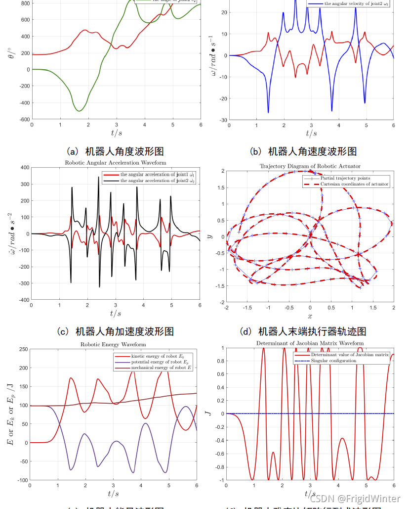
初始状态为 [ θ 1 θ 2 ] = [ 180 ° 0 ° ] \left[ \begin{array}{c} \theta _1\\ \theta _2\\\end{array} \right] =\left[ \begin{array}{c} 180\degree\\ 0\degree\\\end{array} \right] [ θ ˙ 1 θ ˙ 2 ] = [ 0 0 ] \left[ \begin{array}{c} \dot{\theta}_1\\ \dot{\theta}_2\\\end{array} \right] =\left[ \begin{array}{c} 0\\ 0\\\end{array} \right] ,输入力矩为 [ τ 1 τ 2 ] = [ 2 0.5 ] \left[ \begin{array}{c} \tau _1\\ \tau _2\\\end{array} \right] =\left[ \begin{array}{c} 2\\ 0.5\\\end{array} \right] 该初始条件下,平面2R机器人的角度、角速度、角加速度、能量、雅克比矩阵行列式数值波形图以及机器人末端执行器运动轨迹图如图所示

在这里插入图片描述


🔥 更多精彩专栏

🏠 欢迎加入社区和更多志同道合的朋友交流AI 技术社

👇配套代码 · 优质体验 · 系统知识 请关注👇


【版权声明】本文为华为云社区用户原创内容,未经允许不得转载,如需转载请自行联系原作者进行授权。如果您发现本社区中有涉嫌抄袭的内容,欢迎发送邮件进行举报,并提供相关证据,一经查实,本社区将立刻删除涉嫌侵权内容,举报邮箱: cloudbbs@huaweicloud.com
  • 点赞
  • 收藏
  • 关注作者

评论(0

0/1000
抱歉,系统识别当前为高风险访问,暂不支持该操作

全部回复

上滑加载中

设置昵称

在此一键设置昵称,即可参与社区互动!

*长度不超过10个汉字或20个英文字符,设置后3个月内不可修改。

*长度不超过10个汉字或20个英文字符,设置后3个月内不可修改。