小熊派LiteOS移植LVGL
小熊派LiteOS移植LVGL
一、移植前言
之前使用小熊派实现了鸿蒙动画的开机界面,具体使用的技术栈为 STM32 + LiteOS + LVGL + FATFS +DMA 方式实现,刷新效率非常高,预览视频如下:
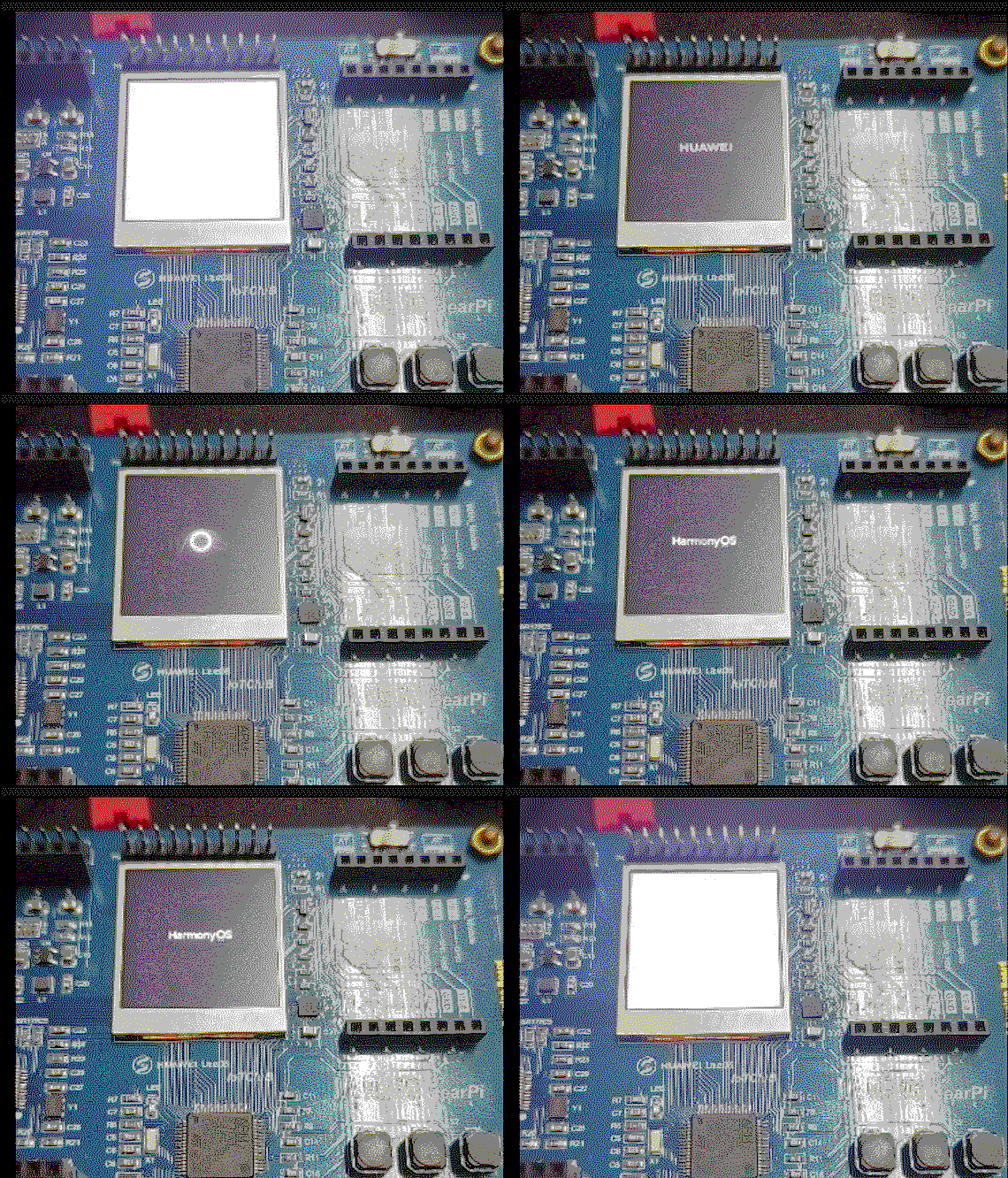
关于这个的实现过程我会写一系列的教程分享出来,主要分为下面几个部分,本节为第二部分,基于 LiteOS 移植 LVGL 显示接口
- 小熊派移植华为 LiteOS-M(基于MDK):链接;
- 小熊派基于 LiteOS 移植 LVGL 显示接口:链接;
- 小熊派基于 LiteOS 移植 LVGL 文件系统:链接;
- 小熊派实现鸿蒙开机界面(LiteOS+LVGL):链接;
本节的教程就是先通过 STM32CubeMX 来配置 小熊派的 TFT 初始化代码,开启 DMA 加速(不开启会卡出翔),配置完成后获取 LVGL 的代码,移植到工程里面,然后将 TFT 驱动接口和 LVGL 接口对接,在运行 Demo 代码
二、配置 TFT
我们在上一节移植好 LiteOS 工程的基础上使用 CubeMX 配置 TFT 的 SPI 接口,具体 SPI 驱动接口可以参考这篇文章:小熊派 FreeRTOS+SPI+DMA 驱动 TFT-LCD
SPI 配置完成如下:
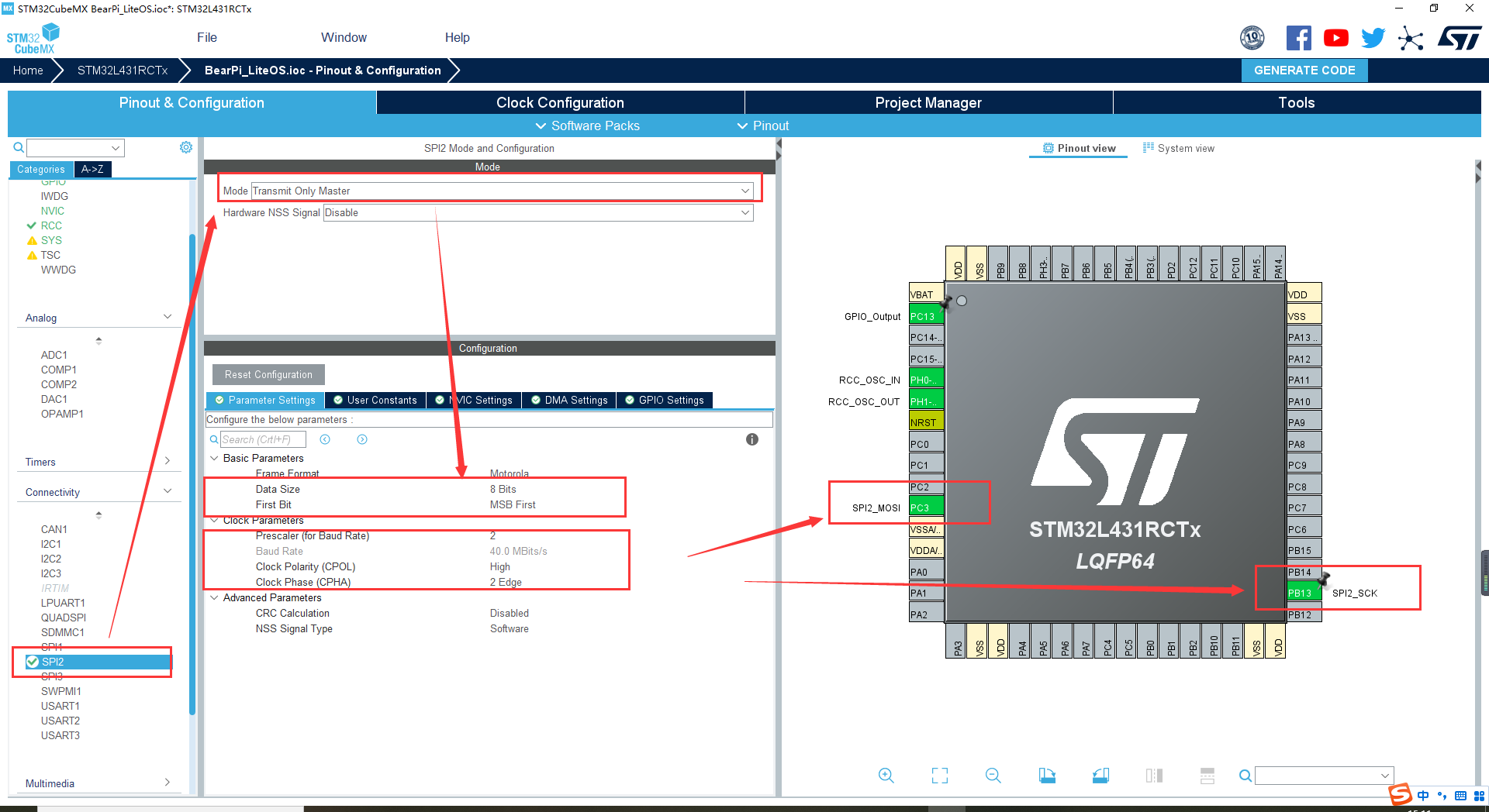
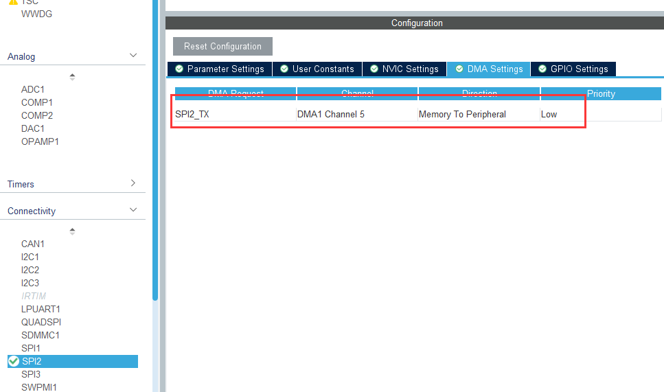
开启 DMA,并且在 NVIC 里面使能中断
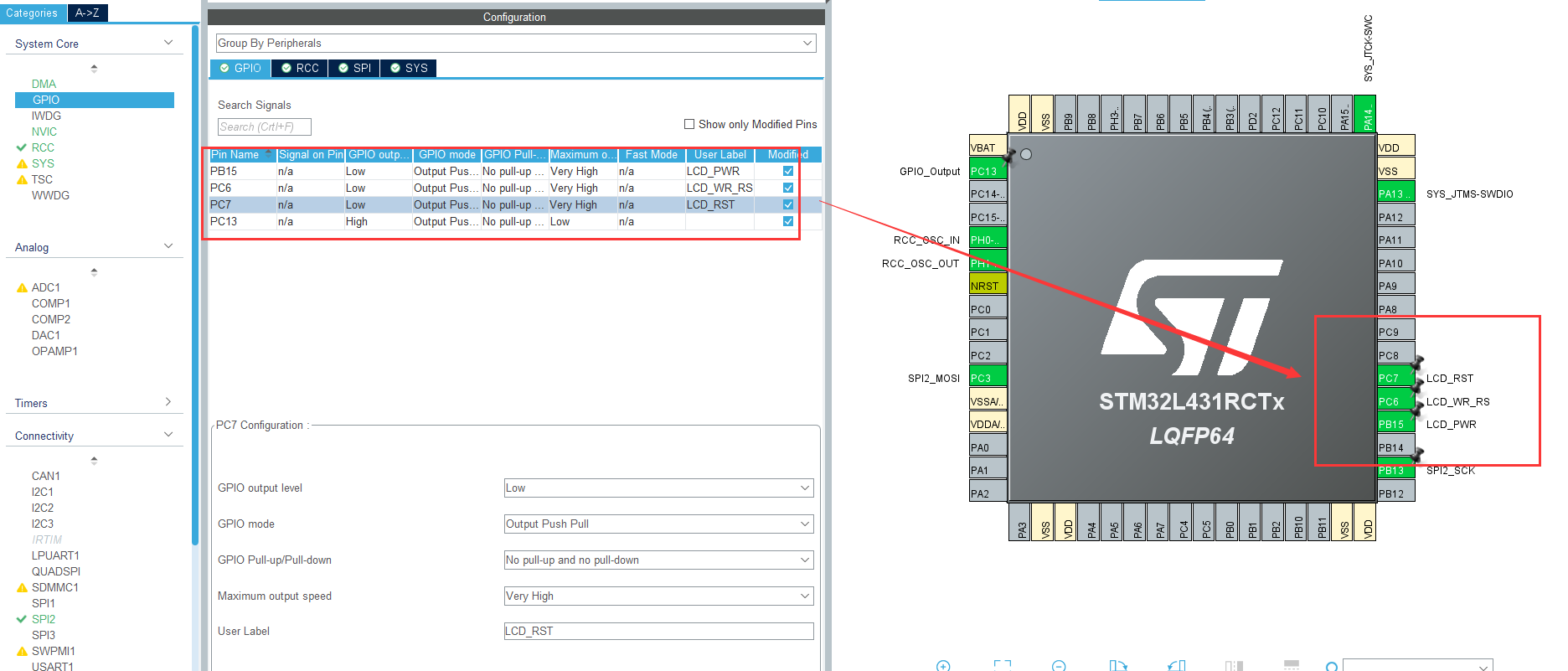
除了上面的 SPI 引脚还需要,配置 TFT 的其他控制引脚,关于引脚在参考文章中有写出来,配置完成如下:
在 MDK 工程根目录下创建 Hardware/LCD 文件夹用来存放驱动代码,驱动文件命名为 lcd.c 和 lcd.h

拷贝下面的代码进去
lcd.c
#include "lcd.h"
#include "gpio.h"
#include "spi.h"
#include "cmsis_os.h"

extern osSemaphoreId_t DMA_SemaphoreHandle;


/* USER CODE BEGIN 1 */
/**
 * @brief    SPI 发送字节函数
 * @param    TxData	要发送的数据
 * @param    size	发送数据的字节大小
 * @return  0:写入成功,其他:写入失败
 */
uint8_t SPI_WriteByte(uint8_t *TxData,uint16_t size)
{

	osStatus_t result;
    //获取信号,如果上一个DMA传输完成
    //信号就能获取到,没有传输完成任务就挂起
    //等到传输完成再恢复
	result = osSemaphoreAcquire(DMA_SemaphoreHandle,0xFFFF);
	if(result == osOK)
	{
		//获取成功
		return HAL_SPI_Transmit_DMA(&hspi2,TxData,size);
	}else
	{
		//获取失败
		return 1;
	}
}
//DMA 传输完成后会调用 SPI传输完成回调函数
//在该函数中我们释放信号
void HAL_SPI_TxCpltCallback(SPI_HandleTypeDef *hspi)
{
	if(hspi->Instance == hspi2.Instance)
		osSemaphoreRelease(DMA_SemaphoreHandle);
}


/**
 * @brief   写命令到LCD
 * @param   cmd —— 需要发送的命令
 * @return  none
 */
static void LCD_Write_Cmd(uint8_t cmd)
{
    LCD_WR_RS(0);
    SPI_WriteByte(&cmd, 1);
}

/**
 * @brief   写数据到LCD
 * @param   dat —— 需要发送的数据
 * @return  none
 */
static void LCD_Write_Data(uint8_t dat)
{
    LCD_WR_RS(1);
    SPI_WriteByte(&dat, 1);
}

/**
 * @breif   打开LCD显示背光
 * @param   none
 * @return  none
 */
void LCD_DisplayOn(void)
{
    LCD_PWR(1);
}
/**
 * @brief   关闭LCD显示背光
 * @param   none
 * @return  none
 */
void LCD_DisplayOff(void)
{
    LCD_PWR(0);
}

/**
 * @brief   设置数据写入LCD显存区域
 * @param   x1,y1	—— 起点坐标
 * @param   x2,y2	—— 终点坐标
 * @return  none
 */
void LCD_Address_Set(uint16_t x1, uint16_t y1, uint16_t x2, uint16_t y2)
{
    /* 指定X方向操作区域 */
    LCD_Write_Cmd(0x2a);
    LCD_Write_Data(x1 >> 8);
    LCD_Write_Data(x1);
    LCD_Write_Data(x2 >> 8);
    LCD_Write_Data(x2);

    /* 指定Y方向操作区域 */
    LCD_Write_Cmd(0x2b);
    LCD_Write_Data(y1 >> 8);
    LCD_Write_Data(y1);
    LCD_Write_Data(y2 >> 8);
    LCD_Write_Data(y2);

    /* 发送该命令,LCD开始等待接收显存数据 */
    LCD_Write_Cmd(0x2C);
}

/**
 * @brief   以一种颜色清空LCD屏
 * @param   color —— 清屏颜色(16bit)
 * @return  none
 */
void LCD_Clear(uint16_t color)
{
    uint16_t i;
    uint8_t data[2] = {0};  //color是16bit的,每个像素点需要两个字节的显存

    /* 将16bit的color值分开为两个单独的字节 */
    data[0] = color >> 8;
    data[1] = color;
    LCD_Address_Set(0, 0, LCD_Width - 1, LCD_Height - 1);
		LCD_WR_RS(1);
		for(i=0;i<((LCD_Width)*(LCD_Height));i++)
		{
			SPI_WriteByte(data, 2);
		}
}

/**
 * @brief   LCD初始化
 * @param   none
 * @return  none
 */
void LCD_Init(void)
{
    /* 复位LCD */
    LCD_PWR(0);
    LCD_RST(0);
    osDelay(100);
    LCD_RST(1);
    osDelay(120);
    /* 关闭睡眠模式 */
    LCD_Write_Cmd(0x11);
    osDelay(120);

    /* 开始设置显存扫描模式,数据格式等 */
    LCD_Write_Cmd(0x36);
    LCD_Write_Data(0x00);
    /* RGB 5-6-5-bit格式  */
    LCD_Write_Cmd(0x3A);
    LCD_Write_Data(0x65);
    /* porch 设置 */
    LCD_Write_Cmd(0xB2);
    LCD_Write_Data(0x0C);
    LCD_Write_Data(0x0C);
    LCD_Write_Data(0x00);
    LCD_Write_Data(0x33);
    LCD_Write_Data(0x33);
    /* VGH设置 */
    LCD_Write_Cmd(0xB7);
    LCD_Write_Data(0x72);
    /* VCOM 设置 */
    LCD_Write_Cmd(0xBB);
    LCD_Write_Data(0x3D);
    /* LCM 设置 */
    LCD_Write_Cmd(0xC0);
    LCD_Write_Data(0x2C);
    /* VDV and VRH 设置 */
    LCD_Write_Cmd(0xC2);
    LCD_Write_Data(0x01);
    /* VRH 设置 */
    LCD_Write_Cmd(0xC3);
    LCD_Write_Data(0x19);
    /* VDV 设置 */
    LCD_Write_Cmd(0xC4);
    LCD_Write_Data(0x20);
    /* 普通模式下显存速率设置 60Mhz */
    LCD_Write_Cmd(0xC6);
    LCD_Write_Data(0x0F);
    /* 电源控制 */
    LCD_Write_Cmd(0xD0);
    LCD_Write_Data(0xA4);
    LCD_Write_Data(0xA1);
    /* 电压设置 */
    LCD_Write_Cmd(0xE0);
    LCD_Write_Data(0xD0);
    LCD_Write_Data(0x04);
    LCD_Write_Data(0x0D);
    LCD_Write_Data(0x11);
    LCD_Write_Data(0x13);
    LCD_Write_Data(0x2B);
    LCD_Write_Data(0x3F);
    LCD_Write_Data(0x54);
    LCD_Write_Data(0x4C);
    LCD_Write_Data(0x18);
    LCD_Write_Data(0x0D);
    LCD_Write_Data(0x0B);
    LCD_Write_Data(0x1F);
    LCD_Write_Data(0x23);
    /* 电压设置 */
    LCD_Write_Cmd(0xE1);
    LCD_Write_Data(0xD0);
    LCD_Write_Data(0x04);
    LCD_Write_Data(0x0C);
    LCD_Write_Data(0x11);
    LCD_Write_Data(0x13);
    LCD_Write_Data(0x2C);
    LCD_Write_Data(0x3F);
    LCD_Write_Data(0x44);
    LCD_Write_Data(0x51);
    LCD_Write_Data(0x2F);
    LCD_Write_Data(0x1F);
    LCD_Write_Data(0x1F);
    LCD_Write_Data(0x20);
    LCD_Write_Data(0x23);
    /* 显示开 */
    LCD_Write_Cmd(0x21);
    LCD_Write_Cmd(0x29);

    /*打开显示*/
    LCD_PWR(1);
}
- 1
- 2
- 3
- 4
- 5
- 6
- 7
- 8
- 9
- 10
- 11
- 12
- 13
- 14
- 15
- 16
- 17
- 18
- 19
- 20
- 21
- 22
- 23
- 24
- 25
- 26
- 27
- 28
- 29
- 30
- 31
- 32
- 33
- 34
- 35
- 36
- 37
- 38
- 39
- 40
- 41
- 42
- 43
- 44
- 45
- 46
- 47
- 48
- 49
- 50
- 51
- 52
- 53
- 54
- 55
- 56
- 57
- 58
- 59
- 60
- 61
- 62
- 63
- 64
- 65
- 66
- 67
- 68
- 69
- 70
- 71
- 72
- 73
- 74
- 75
- 76
- 77
- 78
- 79
- 80
- 81
- 82
- 83
- 84
- 85
- 86
- 87
- 88
- 89
- 90
- 91
- 92
- 93
- 94
- 95
- 96
- 97
- 98
- 99
- 100
- 101
- 102
- 103
- 104
- 105
- 106
- 107
- 108
- 109
- 110
- 111
- 112
- 113
- 114
- 115
- 116
- 117
- 118
- 119
- 120
- 121
- 122
- 123
- 124
- 125
- 126
- 127
- 128
- 129
- 130
- 131
- 132
- 133
- 134
- 135
- 136
- 137
- 138
- 139
- 140
- 141
- 142
- 143
- 144
- 145
- 146
- 147
- 148
- 149
- 150
- 151
- 152
- 153
- 154
- 155
- 156
- 157
- 158
- 159
- 160
- 161
- 162
- 163
- 164
- 165
- 166
- 167
- 168
- 169
- 170
- 171
- 172
- 173
- 174
- 175
- 176
- 177
- 178
- 179
- 180
- 181
- 182
- 183
- 184
- 185
- 186
- 187
- 188
- 189
- 190
- 191
- 192
- 193
- 194
- 195
- 196
- 197
- 198
- 199
- 200
- 201
- 202
- 203
- 204
- 205
- 206
- 207
- 208
- 209
- 210
- 211
- 212
- 213
- 214
- 215
- 216
- 217
- 218
- 219
- 220
- 221
- 222
- 223
- 224
lcd.h
#include "main.h"

#define	LCD_PWR(n)		(n?\
						HAL_GPIO_WritePin(LCD_PWR_GPIO_Port,LCD_PWR_Pin,GPIO_PIN_SET):\
						HAL_GPIO_WritePin(LCD_PWR_GPIO_Port,LCD_PWR_Pin,GPIO_PIN_RESET))
#define	LCD_WR_RS(n)	(n?\
						HAL_GPIO_WritePin(LCD_WR_RS_GPIO_Port,LCD_WR_RS_Pin,GPIO_PIN_SET):\
						HAL_GPIO_WritePin(LCD_WR_RS_GPIO_Port,LCD_WR_RS_Pin,GPIO_PIN_RESET))
#define	LCD_RST(n)		(n?\
						HAL_GPIO_WritePin(LCD_RST_GPIO_Port,LCD_RST_Pin,GPIO_PIN_SET):\
						HAL_GPIO_WritePin(LCD_RST_GPIO_Port,LCD_RST_Pin,GPIO_PIN_RESET))

//LCD屏幕分辨率定义
#define LCD_Width   240
#define LCD_Height  240
//颜色定义
#define WHITE   0xFFFF	//白色
#define YELLOW  0xFFE0	//黄色
#define BRRED   0XFC07  //棕红色
#define PINK    0XF81F	//粉色
#define RED     0xF800	//红色
#define BROWN   0XBC40  //棕色
#define GRAY    0X8430  //灰色
#define GBLUE   0X07FF	//兰色
#define GREEN   0x07E0	//绿色
#define BLUE    0x001F  //蓝色
#define BLACK   0x0000	//黑色

uint8_t SPI_WriteByte(uint8_t *TxData,uint16_t size);
static void LCD_Write_Cmd(uint8_t cmd);
static void LCD_Write_Data(uint8_t dat);
void LCD_DisplayOn(void);
void LCD_DisplayOff(void);
void LCD_Address_Set(uint16_t x1, uint16_t y1, uint16_t x2, uint16_t y2);
void LCD_Clear(uint16_t color);
void LCD_Init(void);
- 1
- 2
- 3
- 4
- 5
- 6
- 7
- 8
- 9
- 10
- 11
- 12
- 13
- 14
- 15
- 16
- 17
- 18
- 19
- 20
- 21
- 22
- 23
- 24
- 25
- 26
- 27
- 28
- 29
- 30
- 31
- 32
- 33
- 34
- 35
- 36
代码和文件添加完成后不要忘记添加文件路径,然后我们在主函数中创建一个用于 lcd 显示的任务,初始化 LCD 同时将屏幕初始化为蓝色
osThreadId_t lcd_taskHandle;
const osThreadAttr_t lcd_task_attributes = {
  .name = "lcd_task",
  .stack_size = 512 * 4,
  .priority = (osPriority_t) osPriorityNormal1,
};
void Lcd_Task(void *argument);
void Lcd_Task(void *argument)
{
	LCD_Init();
	LCD_Clear(BLUE);
	while(1)
	{

		osDelay(1000);
	}
}
- 1
- 2
- 3
- 4
- 5
- 6
- 7
- 8
- 9
- 10
- 11
- 12
- 13
- 14
- 15
- 16
- 17
添加 DMA 信号量
osSemaphoreId_t DMA_SemaphoreHandle;
const osSemaphoreAttr_t DMA_Semaphore_attributes = {
  .name = "DMA_Semaphore"
};
- 1
- 2
- 3
- 4
初始化信号和 LiteOS:
  /* USER CODE BEGIN 2 */
	osKernelInitialize();

  /* creation of uart_task */
	DMA_SemaphoreHandle = osSemaphoreNew(1, 1, &DMA_Semaphore_attributes);
    led_taskHandle = osThreadNew(Led_Task, NULL, &led_task_attributes);
	lcd_taskHandle = osThreadNew(Lcd_Task, NULL, &lcd_task_attributes);
	osKernelStart();
  /* USER CODE END 2 */
- 1
- 2
- 3
- 4
- 5
- 6
- 7
- 8
- 9
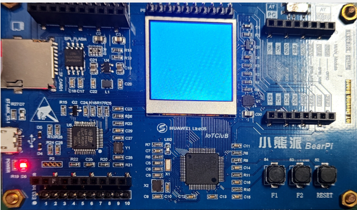
编译烧写程序,观察现象,屏幕清屏为蓝色,驱动程序跑通了,可以进行下一步:
三、LVGL 源码获取
获取 lvgl 7.0 版本的源码
git clone -b release/v7 https://github.com/lvgl/lvgl.git
- 1
拉取后代码
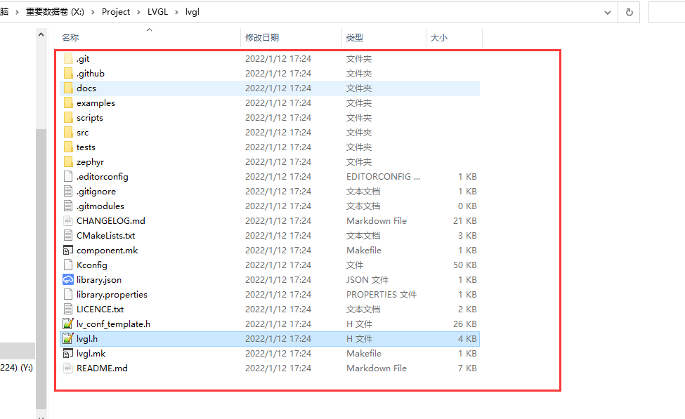
下面我们在 MDK 工程目录按照下面的格式建立文件夹
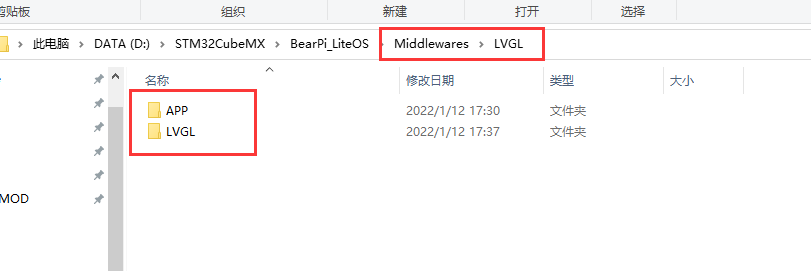
APP 文件夹用来存放我们编写的 lvgl 应用代码,LVGL 文件夹用来存放 lvgl 的源码,以及接口代码
然后我们将刚刚 github 下载的源码拷贝到 LVGL 中,然后把里面 lvgl\examples\porting 文件夹复制到同一目录下,改名为 lvgl_port 文件夹,同时将 lvgl\lv_conf_template.h 也复制到同一目录,并且改名为 lv_conf.h,修改结果如下:

然后将 lvgl_port 下面的文件也修改名称为下面的格式:
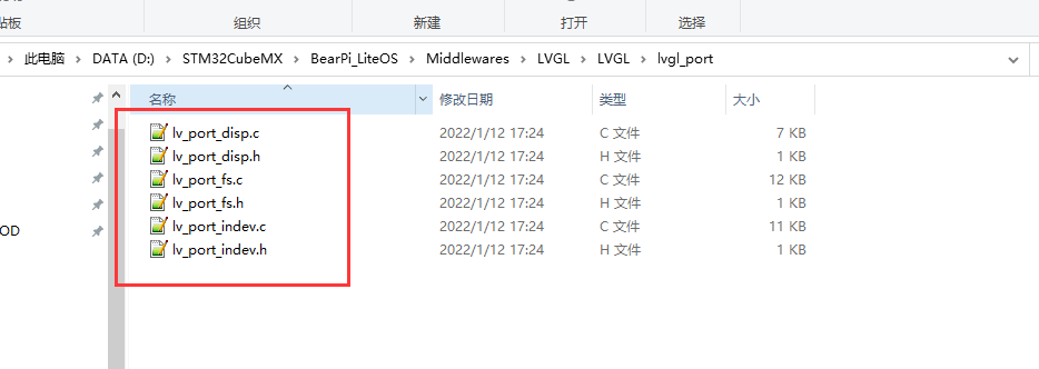
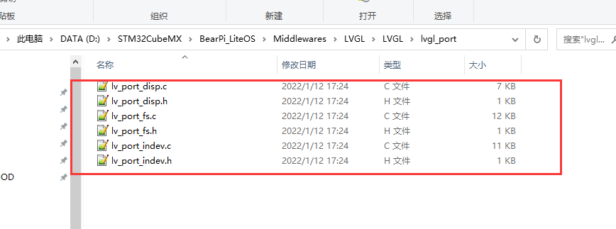
这6个文件是 lvgl 的接口文件,disp 是显示接口、fs 是文件系统接口、indev 是输入接口,下面我们在 MDK 工程里面添加文件和文件路径,添加路径如下:
..\Middlewares\LVGL\APP
..\Middlewares\LVGL\LVGL\lvgl_port
..\Middlewares\LVGL\LVGL\lvgl\src
- 1
- 2
- 3
添加文件如下:
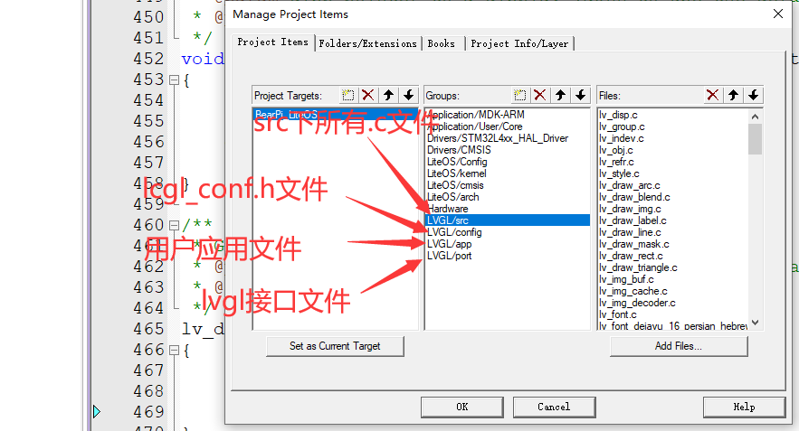
src 放的文件是下面文件夹的所有 c 文件
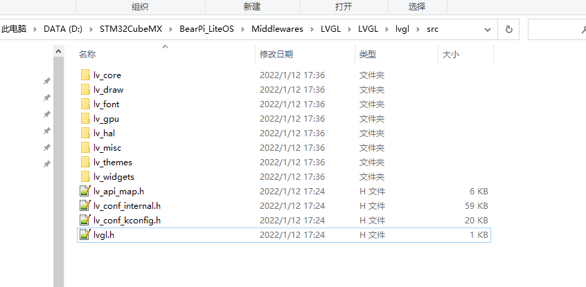
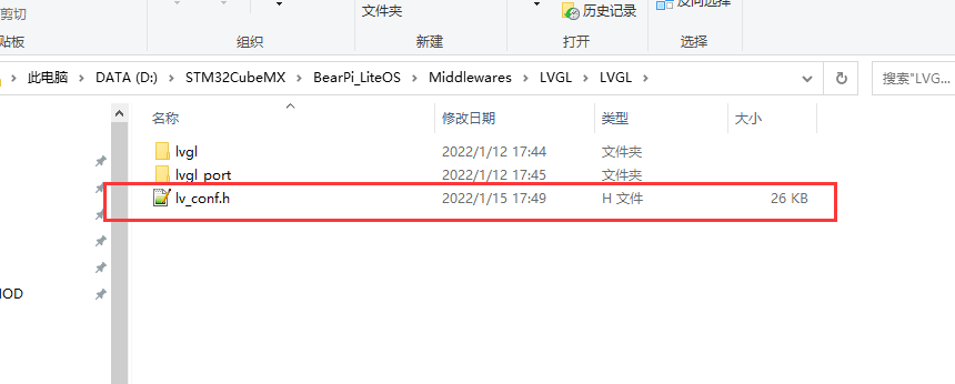
config 放的是 lvgl 配置头文件:
port 放的是 lvgl 的硬件接口文件
文件添加完成后我们先配置 lvgl 下的 lv_conf.h 文件,做一些配置,不然直接编译的话会有一堆报错
lv_conf.h 文件修改:
修改屏幕尺寸适配小熊派:
/* Maximal horizontal and vertical resolution to support by the library.*/
#define LV_HOR_RES_MAX          (240)
#define LV_VER_RES_MAX          (240)
- 1
- 2
- 3
设置屏幕颜色深度,以及颜色存放格式(适配 ST7789芯片):
/* Color depth:
 * - 1:  1 byte per pixel
 * - 8:  RGB332
 * - 16: RGB565
 * - 32: ARGB8888
 */
#define LV_COLOR_DEPTH     16
/* Swap the 2 bytes of RGB565 color.
 * Useful if the display has a 8 bit interface (e.g. SPI)*/
#define LV_COLOR_16_SWAP   1
- 1
- 2
- 3
- 4
- 5
- 6
- 7
- 8
- 9
- 10
设置调节界面缩放比例:
/* Dot Per Inch: used to initialize default sizes.
 * E.g. a button with width = LV_DPI / 2 -> half inch wide
 * (Not so important, you can adjust it to modify default sizes and spaces)*/
#define LV_DPI              60     /*[px]*/
- 1
- 2
- 3
- 4
设置动态内存大小:
/* Size of the memory used by `lv_mem_alloc` in bytes (>= 2kB)*/
#  define LV_MEM_SIZE    (16U * 1024U)
- 1
- 2
关闭使用 GPU:
/* 1: Enable GPU interface*/
#define LV_USE_GPU              0   /*Only enables `gpu_fill_cb` and `gpu_blend_cb` in the disp. drv- */
#define LV_USE_GPU_STM32_DMA2D  0
- 1
- 2
- 3
暂时先关闭文件系统:
/* 1: Enable file system (might be required for images */
#define LV_USE_FILESYSTEM       0
- 1
- 2
编译一下,有一些警告
..\Middlewares\LVGL\LVGL\lvgl\src\lv_draw\lv_draw_mask.c(350): warning: #111-D: statement is unreachable
- 1
这些警告没有任何影响,可以把警告给屏蔽掉,切换到 C/C++选项卡,在 Misc Controls 中填入
--diag_suppress=111 把它屏蔽掉如下图所示:
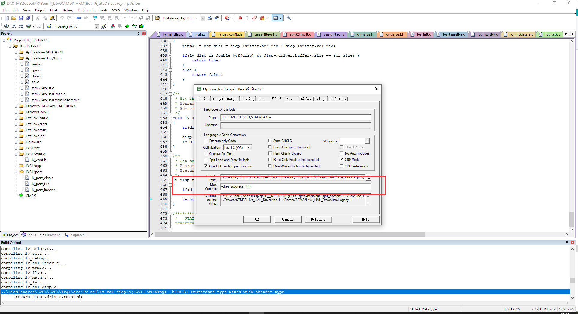
编译后改报错就不显示了
四、显示接口移植
编译通过后,我们下一步就是修改显示接口了,打开 lv_port_disp.c 文件,将开头使能,包括头文件也使能:
 /*Copy this file as "lv_port_disp.c" and set this value to "1" to enable content*/
#if 1
- 1
- 2
修改显示接口,主要关注 void lv_port_disp_init(void) 函数
void lv_port_disp_init(void)
{
    /*-------------------------
     * Initialize your display
     * -----------------------*/
    disp_init();

    /*-----------------------------
     * Create a buffer for drawing
     *----------------------------*/

    /* LVGL requires a buffer where it internally draws the widgets.
     * Later this buffer will passed your display drivers `flush_cb` to copy its content to your display.
     * The buffer has to be greater than 1 display row
     *
     * There are three buffering configurations:
     * 1. Create ONE buffer with some rows:
     *      LVGL will draw the display's content here and writes it to your display
     *
     * 2. Create TWO buffer with some rows:
     *      LVGL will draw the display's content to a buffer and writes it your display.
     *      You should use DMA to write the buffer's content to the display.
     *      It will enable LVGL to draw the next part of the screen to the other buffer while
     *      the data is being sent form the first buffer. It makes rendering and flushing parallel.
     *
     * 3. Create TWO screen-sized buffer:
     *      Similar to 2) but the buffer have to be screen sized. When LVGL is ready it will give the
     *      whole frame to display. This way you only need to change the frame buffer's address instead of
     *      copying the pixels.
     * */

    /* Example for 1) */
    static lv_disp_buf_t draw_buf_dsc_1;
    static lv_color_t draw_buf_1[LV_HOR_RES_MAX * 10];                          /*A buffer for 10 rows*/
    lv_disp_buf_init(&draw_buf_dsc_1, draw_buf_1, NULL, LV_HOR_RES_MAX * 10);   /*Initialize the display buffer*/

    /* Example for 2) */
    static lv_disp_buf_t draw_buf_dsc_2;
    static lv_color_t draw_buf_2_1[LV_HOR_RES_MAX * 10];                        /*A buffer for 10 rows*/
    static lv_color_t draw_buf_2_2[LV_HOR_RES_MAX * 10];                        /*An other buffer for 10 rows*/
    lv_disp_buf_init(&draw_buf_dsc_2, draw_buf_2_1, draw_buf_2_2, LV_HOR_RES_MAX * 10);   /*Initialize the display buffer*/

    /* Example for 3) */
    static lv_disp_buf_t draw_buf_dsc_3;
    static lv_color_t draw_buf_3_1[LV_HOR_RES_MAX * LV_VER_RES_MAX];            /*A screen sized buffer*/
    static lv_color_t draw_buf_3_2[LV_HOR_RES_MAX * LV_VER_RES_MAX];            /*An other screen sized buffer*/
    lv_disp_buf_init(&draw_buf_dsc_3, draw_buf_3_1, draw_buf_3_2, LV_HOR_RES_MAX * LV_VER_RES_MAX);   /*Initialize the display buffer*/

    /*-----------------------------------
     * Register the display in LVGL
     *----------------------------------*/

    lv_disp_drv_t disp_drv;                         /*Descriptor of a display driver*/
    lv_disp_drv_init(&disp_drv);                    /*Basic initialization*/

    /*Set up the functions to access to your display*/

    /*Set the resolution of the display*/
    disp_drv.hor_res = 480;
    disp_drv.ver_res = 320;

    /*Used to copy the buffer's content to the display*/
    disp_drv.flush_cb = disp_flush;

    /*Set a display buffer*/
    disp_drv.buffer = &draw_buf_dsc_1;

#if LV_USE_GPU
    /*Optionally add functions to access the GPU. (Only in buffered mode, LV_VDB_SIZE != 0)*/

    /*Blend two color array using opacity*/
    disp_drv.gpu_blend_cb = gpu_blend;

    /*Fill a memory array with a color*/
    disp_drv.gpu_fill_cb = gpu_fill;
#endif

    /*Finally register the driver*/
    lv_disp_drv_register(&disp_drv);
}
- 1
- 2
- 3
- 4
- 5
- 6
- 7
- 8
- 9
- 10
- 11
- 12
- 13
- 14
- 15
- 16
- 17
- 18
- 19
- 20
- 21
- 22
- 23
- 24
- 25
- 26
- 27
- 28
- 29
- 30
- 31
- 32
- 33
- 34
- 35
- 36
- 37
- 38
- 39
- 40
- 41
- 42
- 43
- 44
- 45
- 46
- 47
- 48
- 49
- 50
- 51
- 52
- 53
- 54
- 55
- 56
- 57
- 58
- 59
- 60
- 61
- 62
- 63
- 64
- 65
- 66
- 67
- 68
- 69
- 70
- 71
- 72
- 73
- 74
- 75
- 76
- 77
- 78
- 79
- 80
disp_init() 用来初始化显示屏外设,这里我们在hal初始化中已经初始化完成了,所以删除他
下面的代码就是创建一个缓存 buffer,这里 LVGL 提供了三种方式创建缓存:
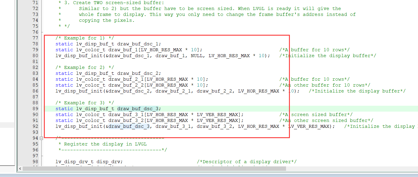
第一种只创建一个缓存区,长度是横轴像素长度的 10 倍,第二种创建两个缓存区,长度都是 横轴的 10 倍,第三种则是创建两个,大小是横轴乘以纵轴,相当于整个屏幕大小,第一种情况,如果我们在写入数据时不能修改,第二种我们在写入一个 buffer 时还可以希尔另外一个 buffer ,可以结合 DMA 加快写入速度,这里我使用第一种
下面的代码注册显示驱动,配置其参数:

主要就是配置屏幕参数,设置刷新函数,配置缓存区指针,最后注册驱动,这里我们要修改一下刷新屏幕函数
static void disp_flush(lv_disp_drv_t * disp_drv, const lv_area_t * area, lv_color_t * color_p)
- 1
修改如下:
/* Flush the content of the internal buffer the specific area on the display
 * You can use DMA or any hardware acceleration to do this operation in the background but
 * 'lv_disp_flush_ready()' has to be called when finished. */
static void disp_flush(lv_disp_drv_t * disp_drv, const lv_area_t * area, lv_color_t * color_p)
{
		/*The most simple case (but also the slowest) to put all pixels to the screen one-by-one*/
		int32_t y;

		LCD_Address_Set(area->x1,area->y1,area->x2,area->y2);
		LCD_WR_RS(1);
		//一行一行 DMA
		for(y = area->y1; y <= area->y2; y++)
		{
			if(osSemaphoreAcquire(DMA_SemaphoreHandle,0xFFFF) == osOK)
				HAL_SPI_Transmit_DMA(&hspi2,(uint8_t *)color_p,(uint16_t)(area->x2-area->x1+1)*2);
			color_p += (area->x2-area->x1+1);
		}
    /* IMPORTANT!!!
     * Inform the graphics library that you are ready with the flushing*/
    lv_disp_flush_ready(disp_drv);
}
- 1
- 2
- 3
- 4
- 5
- 6
- 7
- 8
- 9
- 10
- 11
- 12
- 13
- 14
- 15
- 16
- 17
- 18
- 19
- 20
- 21
修改代码后,要添加头文件和 dma 信号量声明
/*********************
 *      INCLUDES
 *********************/
#include "lv_port_disp.h"
#include "lcd.h"
#include "spi.h"
#include "cmsis_os.h"
/*********************
 *      DEFINES
 *********************/
extern osSemaphoreId_t DMA_SemaphoreHandle;
- 1
- 2
- 3
- 4
- 5
- 6
- 7
- 8
- 9
- 10
- 11
五、Demo 代码
在定时器 1 中断中添加 lvgl 的时基更新代码
void TIM1_UP_TIM16_IRQHandler(void)
{
  /* USER CODE BEGIN TIM1_UP_TIM16_IRQn 0 */

  /* USER CODE END TIM1_UP_TIM16_IRQn 0 */
  HAL_TIM_IRQHandler(&htim1);
  /* USER CODE BEGIN TIM1_UP_TIM16_IRQn 1 */
	lv_tick_inc(1);
  /* USER CODE END TIM1_UP_TIM16_IRQn 1 */
}
- 1
- 2
- 3
- 4
- 5
- 6
- 7
- 8
- 9
- 10
在 main.c 的 lcd 任务中添加创建 label 测试的代码
这里的测试代码是画两个对角位置的方块,边框颜色都不一样,一个设置的是蓝色,一个是绿色
void Lcd_Task(void *argument)
{
	LCD_Init();

	lv_init();
	lv_port_disp_init();//lvgl 显示接口初始化,放在 lv_init()的后面

	lv_style_t style1;
	lv_style_init(&style1);
	lv_style_set_bg_color(&style1, LV_STATE_DEFAULT,LV_COLOR_BLACK);
	lv_style_set_border_width(&style1,LV_STATE_DEFAULT, 5);
	lv_style_set_border_color(&style1,LV_STATE_DEFAULT, LV_COLOR_BLUE);

	lv_style_t style2;
	lv_style_init(&style2);
	lv_style_set_bg_color(&style2, LV_STATE_DEFAULT,LV_COLOR_BLACK);
	lv_style_set_border_width(&style2,LV_STATE_DEFAULT, 5);
	lv_style_set_border_color(&style2,LV_STATE_DEFAULT, LV_COLOR_GREEN);

	lv_obj_t* bgk1 = lv_obj_create(lv_scr_act(), NULL);//创建对象
	lv_obj_set_pos(bgk1,0,0);
	lv_obj_set_size(bgk1, 120, 120);//设置覆盖大小
	lv_obj_add_style(bgk1,LV_STATE_DEFAULT, &style1);


	lv_obj_t* bgk2 = lv_obj_create(lv_scr_act(), NULL);//创建对象
	lv_obj_set_pos(bgk2,120,120);
	lv_obj_set_size(bgk2, 120, 120);//设置覆盖大小
	lv_obj_add_style(bgk2,LV_STATE_DEFAULT, &style2);

	while(1)
	{
		lv_task_handler();
		osDelay(1000);
	}
}
/* USER CODE END 0 */
- 1
- 2
- 3
- 4
- 5
- 6
- 7
- 8
- 9
- 10
- 11
- 12
- 13
- 14
- 15
- 16
- 17
- 18
- 19
- 20
- 21
- 22
- 23
- 24
- 25
- 26
- 27
- 28
- 29
- 30
- 31
- 32
- 33
- 34
- 35
- 36
- 37
记得添加相关头文件:
/* USER CODE BEGIN Includes */
#include "cmsis_os.h"
#include "lcd.h"
#include "lv_port_disp.h"
/* USER CODE END Includes */
- 1
- 2
- 3
- 4
- 5
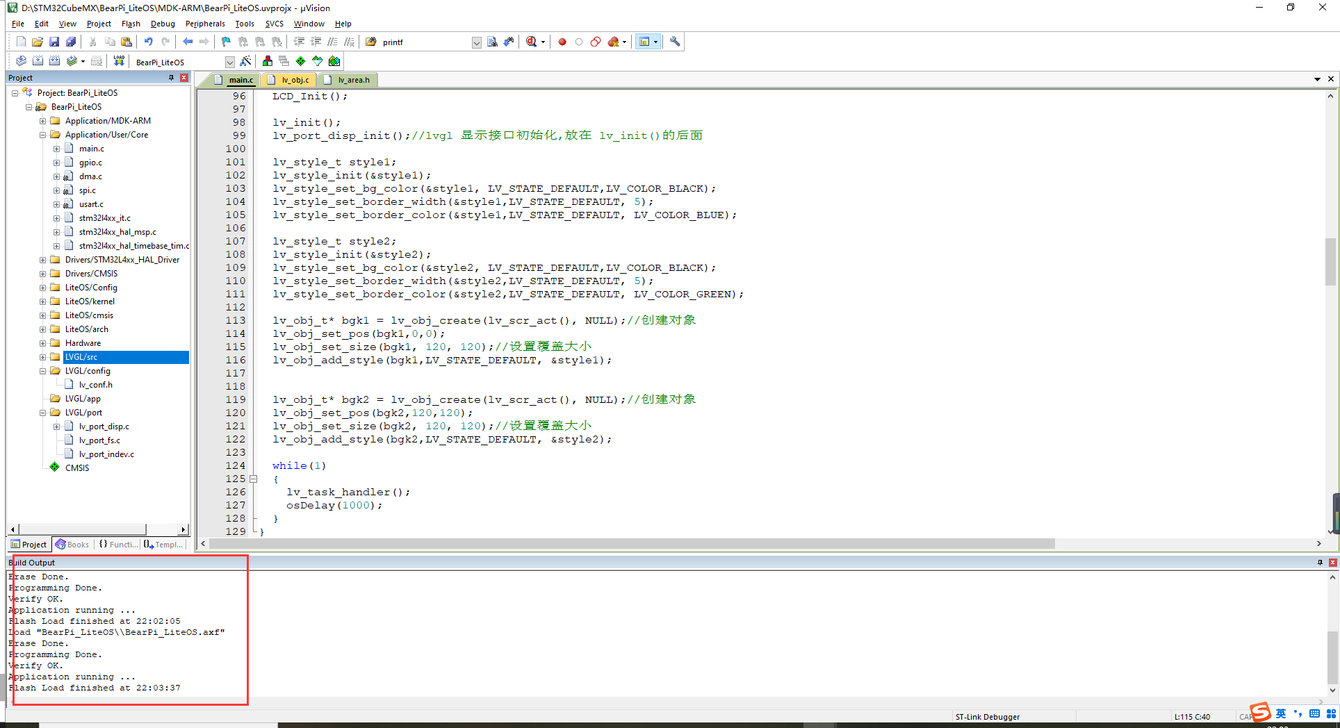
编译下载代码
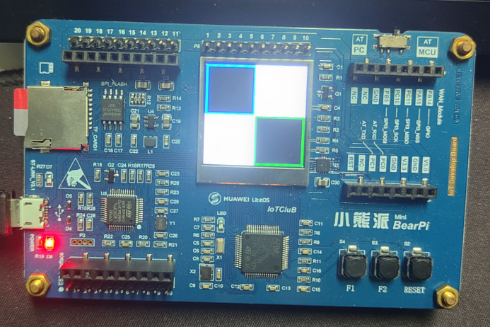
六、实验现象
两个对角小方块,边框一个蓝色一个绿色
文章来源: blog.csdn.net,作者:JeckXu666,版权归原作者所有,如需转载,请联系作者。
原文链接:blog.csdn.net/qq_45396672/article/details/122529954
- 点赞
- 收藏
- 关注作者


评论(0)