Linux系统移植:U-Boot 启动流程(上)
Linux系统移植:U-Boot 启动流程(上)
一、reset 函数源码详解
根据链接文件,可以知道 U-Boot 的入口点是 arch/arm/lib/vectors.S 文件中的 _start,函数代码第一句是跳转到 reset 函数
_start:

#ifdef CONFIG_SYS_DV_NOR_BOOT_CFG
	.word	CONFIG_SYS_DV_NOR_BOOT_CFG
#endif

	b	reset
	...
- 1
- 2
- 3
- 4
- 5
- 6
- 7
- 8
reset 函数在 arch/arm/cpu/armv7/start.S 里面,代码如下,函数跳转到了 save_boot_params
reset:
	/* Allow the board to save important registers */
	b	save_boot_params
- 1
- 2
- 3
save_boot_params 函数又跳了一次,到了 save_boot_params_ret
ENTRY(save_boot_params)
	b	save_boot_params_ret		@ back to my caller
- 1
- 2
save_boot_params_ret 函数如下:
save_boot_params_ret:
	/*
	 * disable interrupts (FIQ and IRQ), also set the cpu to SVC32 mode,
	 * except if in HYP mode already
	 */
	mrs	r0, cpsr
	and	r1, r0, #0x1f		@ mask mode bits
	teq	r1, #0x1a		@ test for HYP mode
	bicne	r0, r0, #0x1f		@ clear all mode bits
	orrne	r0, r0, #0x13		@ set SVC mode
	orr	r0, r0, #0xc0		@ disable FIQ and IRQ
	msr	cpsr,r0
- 1
- 2
- 3
- 4
- 5
- 6
- 7
- 8
- 9
- 10
- 11
- 12
此处代码读取寄存器 cpsr 中的值,并保存到 r0 寄存器,然后将寄存器 r0 中的值与 0X1F 进行与运算,结果保存到 r1 寄存器,这段代码就是提取 cpsr 的 bit0~bit4 这 5 位,获得处理器的工作模式:
| M[4:0] | 模式 |
|---|---|
| 10000 | User(usr) |
| 10001 | FIQ(fiq) |
| 10010 | IRQ(irq) |
| 10011 | Supervisor(svc) |
| 10110 | Monitor(mon) |
| 10111 | Abort(abt) |
| 11010 | Hyp(hyp) |
| 11011 | Undefined(und) |
| 11111 | System(sys) |
然后代码判断 r1 寄存器的值是否等于 0X1A,判断当前处理器模式是否处于 Hyp 模式,如果不为 Hyp 模式的话就将 r0 寄存器的 bit0~5 进行清零
后面的代码将 r0 的寄存器的值与 0x13 进行或运算,设置处理器进入 SVC 模式,r0 寄存器的值再与 0xC0 进行或运算,因为 cpsr 的 I 为和 F 位分别控制 IRQ 和 FIQ 这两个中断的开关,设置为 1 就关闭了 FIQ 和 IRQ,然后将 r0 寄存器写回到 cpsr 寄存器中
所以这段代码的功能就是设置 CPU 处于 SVC32 模式,并且关闭 FIQ 和 IRQ 这两个中断
后面的代码
#if !(defined(CONFIG_OMAP44XX) && defined(CONFIG_SPL_BUILD))
	/* Set V=0 in CP15 SCTLR register - for VBAR to point to vector */
	mrc	p15, 0, r0, c1, c0, 0	@ Read CP15 SCTLR Register
	bic	r0, #CR_V		@ V = 0
	mcr	p15, 0, r0, c1, c0, 0	@ Write CP15 SCTLR Register

	/* Set vector address in CP15 VBAR register */
	ldr	r0, =_start
	mcr	p15, 0, r0, c12, c0, 0	@Set VBAR
#endif
- 1
- 2
- 3
- 4
- 5
- 6
- 7
- 8
- 9
- 10
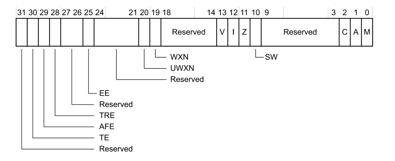
判断没有定义 CONFIG_OMAP44XX 和 CONFIG_SPL_BUILD 的话条件成立,执行下面的代码,读取 CP15 协处理器中 c1 寄存器的值到 r0 寄存器中,这里读取的是协处理器 SCTLR 寄存器的值,然后用 CR_V 清除 SCTLR 寄存器中的 bit13 位

此位是向量表控制位,当为 0 的时候向量表基地址为 0X00000000,软件可以重定位向量表。为 1 的时候向量表基地址为 0XFFFF0000,软件不能重定位向量表。这里将 V 清零,为了接下来的向量表重定位,然后将 r0 寄存器的值重写写入到寄存器 SCTLR 中
后面的代码设置 r0 寄存器的值为 _start,_start 就是整个uboot 的入口地址,其值为 0X87800000,相当于 uboot 的起始地址,因此 0x87800000 也是向量表的起始地址
后面的代码分别调用函数 cpu_init_cp15、cpu_init_crit 和 _main 函数
	/* the mask ROM code should have PLL and others stable */
#ifndef CONFIG_SKIP_LOWLEVEL_INIT
	bl	cpu_init_cp15
	bl	cpu_init_crit
#endif

	bl	_main
- 1
- 2
- 3
- 4
- 5
- 6
- 7
cpu_init_cp15 用来设置 CP15 相关的内容,初始化协处理器,具体代码可以在 start.S 里面找
而函数 cpu_init_crit 内部仅仅是调用了函数 lowlevel_init,下面分析一下 lowlevel_init 函数
二、lowlevel_init 函数详解
函数 lowlevel_init 在文件 arch/arm/cpu/armv7/lowlevel_init.S 中定义,代码如下:
ENTRY(lowlevel_init)
	/*
	 * Setup a temporary stack. Global data is not available yet.
	 */
	ldr	sp, =CONFIG_SYS_INIT_SP_ADDR
	bic	sp, sp, #7 /* 8-byte alignment for ABI compliance */
#ifdef CONFIG_SPL_DM
	mov	r9, #0
#else
	/*
	 * Set up global data for boards that still need it. This will be
	 * removed soon.
	 */
#ifdef CONFIG_SPL_BUILD
	ldr	r9, =gdata
#else
	sub	sp, sp, #GD_SIZE
	bic	sp, sp, #7
	mov	r9, sp
#endif
#endif
	/*
	 * Save the old lr(passed in ip) and the current lr to stack
	 */
	push	{ip, lr}

	/*
	 * Call the very early init function. This should do only the
	 * absolute bare minimum to get started. It should not:
	 *
	 * - set up DRAM
	 * - use global_data
	 * - clear BSS
	 * - try to start a console
	 *
	 * For boards with SPL this should be empty since SPL can do all of
	 * this init in the SPL board_init_f() function which is called
	 * immediately after this.
	 */
	bl	s_init
	pop	{ip, pc}
ENDPROC(lowlevel_init)
- 1
- 2
- 3
- 4
- 5
- 6
- 7
- 8
- 9
- 10
- 11
- 12
- 13
- 14
- 15
- 16
- 17
- 18
- 19
- 20
- 21
- 22
- 23
- 24
- 25
- 26
- 27
- 28
- 29
- 30
- 31
- 32
- 33
- 34
- 35
- 36
- 37
- 38
- 39
- 40
- 41
- 42
代码就是设置 sp 指向 CONFIG_SYS_INIT_SP_ADDR,CONFIG_SYS_INIT_SP_ADDR 在 include/configs/mx6ullevk.h 文件中,定义如下:
    #define CONFIG_SYS_INIT_RAM_ADDR IRAM_BASE_ADDR
    #define CONFIG_SYS_INIT_RAM_SIZE IRAM_SIZE

    #define CONFIG_SYS_INIT_SP_OFFSET \
    (CONFIG_SYS_INIT_RAM_SIZE - GENERATED_GBL_DATA_SIZE)
    #define CONFIG_SYS_INIT_SP_ADDR \
    (CONFIG_SYS_INIT_RAM_ADDR + CONFIG_SYS_INIT_SP_OFFSET)
- 1
- 2
- 3
- 4
- 5
- 6
- 7
IRAM_BASE_ADDR 和 IRAM_SIZE 在文件 arch/arm/include/asm/arch-mx6/imx-regs.h 中有定义,用于设置 ocram 的首地址和大小
#define IRAM_BASE_ADDR 0x00900000

#if !(defined(CONFIG_MX6SX) || defined(CONFIG_MX6UL) || \
	defined(CONFIG_MX6SLL) || defined(CONFIG_MX6SL))
	#define IRAM_SIZE 0x00040000
#else
	#define IRAM_SIZE 0x00020000
#endif
- 1
- 2
- 3
- 4
- 5
- 6
- 7
- 8
所以
CONFIG_SYS_INIT_RAM_ADDR = IRAM_BASE_ADDR = 0x00900000。
CONFIG_SYS_INIT_RAM_SIZE = 0x00020000 =128KB
- 1
- 2
而 GENERATED_GBL_DATA_SIZE 在 include/generated/generic-asm-offsets.h 中有定义
#define GENERATED_GBL_DATA_SIZE 256
- 1
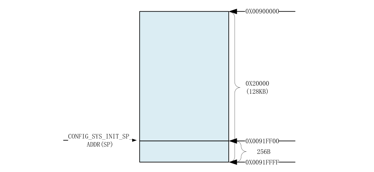
所以设置后 SP 如下,此时 sp 指向 0X91FF00,这属于 IMX6UL/IMX6ULL 的内部 ram

后面的代码进行8字节对齐:
bic sp, sp, #7 /* 8-byte alignment for ABI compliance */
- 1
然后 sp 指针减去 GD_SIZE,GD_SIZE 同样在 generic-asm-offsets.h 中定了,大小为 248,然后同样做8字节对齐:
#ifdef CONFIG_SPL_BUILD
	ldr	r9, =gdata
#else
	sub	sp, sp, #GD_SIZE
	bic	sp, sp, #7
	mov	r9, sp
#endif
- 1
- 2
- 3
- 4
- 5
- 6
- 7
bic sp, sp, #7 实现8位对齐的原理就是将最低三位清零因为 #7 对应 (0111),清除后就可以被 8 (1000)整除,不过前提是栈地址要向下生长,这样被清除的地址不会与数据冲突
后面的代码将 sp 地址保存在 r9 寄存器中,然后将 ip 和 lr 压栈,然后调用函数 s_init,调用完成后,将入栈的 ip 和 lr 进行出栈,并将 lr 赋给 pc
三、s_init 函数详解
s_init 函数定义在文件 arch/arm/cpu/armv7/mx6/soc.c 中,函数部分代码如下:
void s_init(void)
{
	struct anatop_regs *anatop = (struct anatop_regs *)ANATOP_BASE_ADDR;
	struct mxc_ccm_reg *ccm = (struct mxc_ccm_reg *)CCM_BASE_ADDR;
	u32 mask480;
	u32 mask528;
	u32 reg, periph1, periph2;

	if (is_cpu_type(MXC_CPU_MX6SX) || is_cpu_type(MXC_CPU_MX6UL) ||
	    is_cpu_type(MXC_CPU_MX6ULL) || is_cpu_type(MXC_CPU_MX6SLL))
		return;

	//代码省略...
}
- 1
- 2
- 3
- 4
- 5
- 6
- 7
- 8
- 9
- 10
- 11
- 12
- 13
- 14
代码判断当前 CPU 类型,如果 CPU 为 MX6SX、MX6UL、MX6ULL 或 MX6SLL 中的任意 一 种 , 那么就会直接返回:
	if (is_cpu_type(MXC_CPU_MX6SX) || is_cpu_type(MXC_CPU_MX6UL) ||
	    is_cpu_type(MXC_CPU_MX6ULL) || is_cpu_type(MXC_CPU_MX6SLL))
		return;
- 1
- 2
- 3
所以对 I.MX6UL/I.MX6ULL 来说,s_init 就是个空函数,所以到此 lowlevel_init 函数执行完成了,执行如下:

下一个要执行的函数就是 _main 函数
四、_main 函数详解
_main 函数定义在文件 arch/arm/lib/crt0.S 中
代码首先设置 sp 指针为 CONFIG_SYS_INIT_SP_ADDR,就是 sp 指向 0X0091FF00,然后 sp 做 8 字节对齐,然后读取 sp 到寄存器 r0 里面,调用 board_init_f_alloc_reserve 函数,r0 中的 sp 值作为函数参数,函数调用后返回值再通过 r0 传给 sp :
#if defined(CONFIG_SPL_BUILD) && defined(CONFIG_SPL_STACK)
	ldr	sp, =(CONFIG_SPL_STACK)
#else
	ldr	sp, =(CONFIG_SYS_INIT_SP_ADDR)
#endif
#if defined(CONFIG_CPU_V7M)	/* v7M forbids using SP as BIC destination */
	mov	r3, sp
	bic	r3, r3, #7
	mov	sp, r3
#else
	bic	sp, sp, #7	/* 8-byte alignment for ABI compliance */
#endif
	mov	r0, sp
	bl	board_init_f_alloc_reserve
	mov	sp, r0
- 1
- 2
- 3
- 4
- 5
- 6
- 7
- 8
- 9
- 10
- 11
- 12
- 13
- 14
- 15
board_init_f_alloc_reserve 函数定义在文件 common/init/board_init.c,代码如下:
ulong board_init_f_alloc_reserve(ulong top)
{
	/* Reserve early malloc arena */
#if defined(CONFIG_SYS_MALLOC_F)
	top -= CONFIG_SYS_MALLOC_F_LEN;
#endif
	/* LAST : reserve GD (rounded up to a multiple of 16 bytes) */
	top = rounddown(top-sizeof(struct global_data), 16);

	return top;
}
- 1
- 2
- 3
- 4
- 5
- 6
- 7
- 8
- 9
- 10
- 11
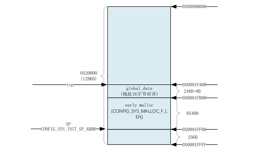
函数 board_init_f_alloc_reserve 主要是留出早期的 malloc 内存区域和 gd 内存区域,malloc 的大小 CONFIG_SYS_MALLOC_F_LEN=0X400( 在 文 件include/generated/autoconf.h 中 定 义 )
执行完成后,函数的指针如下:

后面的代码将 r0 寄存器的值写到寄存器 r9 里面
	/* set up gd here, outside any C code */
	mov	r9, r0
- 1
- 2
r9 寄存器存放着全局变量 gd 的地址,gd 是一个指向 gd_t 的指针,gd_t 是个结构体,部分定义如下:
typedef struct global_data {
	bd_t *bd;
	unsigned long flags;
	unsigned int baudrate;
	unsigned long cpu_clk;	/* CPU clock in Hz!		*/
	unsigned long bus_clk;
	/* We cannot bracket this with CONFIG_PCI due to mpc5xxx */
	unsigned long pci_clk;
	unsigned long mem_clk;
#if defined(CONFIG_LCD) || defined(CONFIG_VIDEO)
	unsigned long fb_base;	/* Base address of framebuffer mem */
#endif
//.......................//
- 1
- 2
- 3
- 4
- 5
- 6
- 7
- 8
- 9
- 10
- 11
- 12
- 13
后面的代码调用函数 board_init_f_init_reserve ,此函数用于初始化 gd,其实就是清零处理,此函数还设置了
gd->malloc_base 为 gd 基地址+gd 大小=0X0091FA00+248=0X0091FAF8,在做 16 字节对齐,最终 gd->malloc_base=0X0091FB00,这个也就是 early malloc 的起始地址
bl board_init_f_init_reserve
- 1
然后设置 R0 为 0,再调用 board_init_f 函数,此函数定义在文件 common/board_f.c 中,主要用来初始化 DDR、定时器、完成代码拷贝等等操作
	mov	r0, #0
	bl	board_init_f
- 1
- 2
后面的代码如下:
#if ! defined(CONFIG_SPL_BUILD)

/*
 * Set up intermediate environment (new sp and gd) and call
 * relocate_code(addr_moni). Trick here is that we'll return
 * 'here' but relocated.
 */

	ldr	sp, [r9, #GD_START_ADDR_SP]	/* sp = gd->start_addr_sp */
#if defined(CONFIG_CPU_V7M)	/* v7M forbids using SP as BIC destination */
	mov	r3, sp
	bic	r3, r3, #7
	mov	sp, r3
#else
	bic	sp, sp, #7	/* 8-byte alignment for ABI compliance */
#endif
	ldr	r9, [r9, #GD_BD]		/* r9 = gd->bd */
	sub	r9, r9, #GD_SIZE		/* new GD is below bd */

	adr	lr, here
	ldr	r0, [r9, #GD_RELOC_OFF]		/* r0 = gd->reloc_off */
	add	lr, lr, r0
#if defined(CONFIG_CPU_V7M)
	orr	lr, #1				/* As required by Thumb-only */
#endif
	ldr	r0, [r9, #GD_RELOCADDR]		/* r0 = gd->relocaddr */
	b	relocate_code
here:
/*
 * now relocate vectors
 */

	bl	relocate_vectors

/* Set up final (full) environment */

	bl	c_runtime_cpu_setup	/* we still call old routine here */
#endif
- 1
- 2
- 3
- 4
- 5
- 6
- 7
- 8
- 9
- 10
- 11
- 12
- 13
- 14
- 15
- 16
- 17
- 18
- 19
- 20
- 21
- 22
- 23
- 24
- 25
- 26
- 27
- 28
- 29
- 30
- 31
- 32
- 33
- 34
- 35
- 36
- 37
- 38
代码先获取 gd->start_addr_sp 的值赋给 sp,这里相当于设置 sp=gd->start_addr_sp=0X9EF44E90,0X9EF44E90 是 DDR 中的地址,说明新的 sp 和 gd 将会存放到 DDR 中,而不是内部的 RAM 了
然后借助 r3 寄存器对 sp 做 8 字节对齐,之后获取 gd->bd 的地址赋给 r9,此时 r9 存放的是老的 gd,这里通过获取 gd->bd 的地址来计算出新的 gd 的位置
lr 寄存器的值加上 r0 寄存器的值,重新赋值给 lr 寄存器。因为接下来要重定位代码,也就是把代码拷贝到新的地方去(现在的 uboot 存放的起始地址为 0X87800000,下面要将 uboot 拷贝到 DDR 最后面的地址空间出,将 0X87800000 开始的内存空出来),其中就包括 here,因此 lr 中的 here 要使用重定位后的位置
之后读取 gd->relocaddr 的值赋给 r0 寄存器,此时 r0 寄存器就保存着 uboot 要拷贝的目的地址,作为参数,调用函数 relocate_code(代码重定位函数),执行完成后调用函数 c_runtime_cpu_setup 用来配置协处理器
下面的代码用来清除 BSS 段
	ldr	r0, =__bss_start	/* this is auto-relocated! */

#ifdef CONFIG_USE_ARCH_MEMSET
	ldr	r3, =__bss_end		/* this is auto-relocated! */
	mov	r1, #0x00000000		/* prepare zero to clear BSS */

	subs	r2, r3, r0		/* r2 = memset len */
	bl	memset
#else
	ldr	r1, =__bss_end		/* this is auto-relocated! */
	mov	r2, #0x00000000		/* prepare zero to clear BSS */

clbss_l:cmp	r0, r1			/* while not at end of BSS */
#if defined(CONFIG_CPU_V7M)
	itt	lo
#endif
	strlo	r2, [r0]		/* clear 32-bit BSS word */
	addlo	r0, r0, #4		/* move to next */
	blo	clbss_l
#endif
- 1
- 2
- 3
- 4
- 5
- 6
- 7
- 8
- 9
- 10
- 11
- 12
- 13
- 14
- 15
- 16
- 17
- 18
- 19
- 20
后面的代码
	mov     r0, r9                  /* gd_t */
	ldr	r1, [r9, #GD_RELOCADDR]	/* dest_addr */
- 1
- 2
设置函数 board_init_r 的两个参数,然后调用函数:
#if defined(CONFIG_SYS_THUMB_BUILD)
	ldr	lr, =board_init_r	/* this is auto-relocated! */
	bx	lr
#else
	ldr	pc, =board_init_r	/* this is auto-relocated! */
#endif
	/* we should not return here. */
#endif
- 1
- 2
- 3
- 4
- 5
- 6
- 7
- 8
然后 _main 函数就调用结束了,在 _main 函数里面调用了 board_init_f、relocate_code、relocate_vectors 和 board_init_r 这 4 个函数,下一节分析一下这四个函数功能
总结一下这段代码的执行流程就是
- 上电启动后,代码执行到 _start 函数,调用 reset 函数,reset 的函数目的是将处理器设置为SVC模式,并且关闭FIQ和IRQ,然后设置中断向量以及初始化 CP15 协处理器
- 然后 lowlevel_init 设置SP指针、R9 寄存器(gd 结构体指针值)
- 之后在 _main 函数里面修改 SP 指针,重定位代码,以及初始化 BSS 段
文章来源: blog.csdn.net,作者:JeckXu666,版权归原作者所有,如需转载,请联系作者。
原文链接:blog.csdn.net/qq_45396672/article/details/122111766
- 点赞
- 收藏
- 关注作者


评论(0)